
Signal synchronization tapping plate for ink jet printer and signal transmission method

An inkjet printer and signal synchronization technology, applied in printing devices, printing, etc., can solve problems such as spray head lagging, affecting inkjet effect, time interval, etc., and achieve the effect of increasing printing width, improving inkjet quality, and increasing printing speed

Active Publication Date: 2014-09-24
BEIJING MEIKEYI
View PDF9 Cites 27 Cited by
  • Summary
  • Abstract
  • Description
  • Claims
  • Application Information

AI Technical Summary

Problems solved by technology

When each nozzle starts to eject ink droplets is determined by the received detection signals, one of which is the starting position signal of the printing medium page detected by the sensor, and the other signal is the raster signal detected by the encoder. After the detected signal is transmitted to the print head control board, the host computer sends the print start command through the CAN bus to control the print head to start ink ejection. According to the receiving address of the board, the start print command is first passed to the first print head control board, and then the start print The command is passed to the second print head control board, and so on, until the print start command is passed to the last print head control board, because different print head control boards receive the start print command sent by the host successively, so the moment of receiving the start print command will appear A small time interval, so that the start printing command received by the print head connected to the print head control board is asynchronous, which may cause the spray head to lag after receiving the start print command and affect the printing effect

Method used


Image

  • Signal synchronization tapping plate for ink jet printer and signal transmission method
  • Signal synchronization tapping plate for ink jet printer and signal transmission method
  • Signal synchronization tapping plate for ink jet printer and signal transmission method

Examples


Embodiment Construction

[0024] In order to make the object, technical solution and advantages of the present invention clearer, the present invention will be further described in detail below in conjunction with the accompanying drawings and embodiments. It should be understood that the specific embodiments described here are only used to explain the present invention, not to limit the present invention.

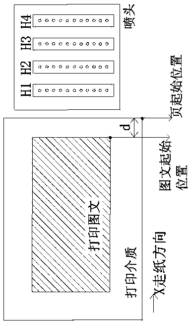
[0025] figure 1 It is a schematic diagram of the corresponding relationship between the printing nozzle and the printing medium in the present invention. During the Onepass printing process, the printing medium is conveyed along the X-axis direction, the position of the nozzle is fixed, and the printing nozzle passes through the printing nozzle at the preset position of the printing medium to be printed. When it is down, the nozzle performs inkjet printing. In order to ensure the correct ink ejection time of the nozzle, it is necessary to detect the conveying position of the printing medium during...


PUM


Abstract

The invention discloses a signal synchronization tapping plate for an ink jet printer and a signal transmission method. The tapping plate is characterized in that one end is provided with a receiving port for receiving a detection signal, and the other end is provided with an output port connecting nozzle control boards for outputting a detection signal; the interior of the tapping plate is provided with an FPGA which divides the received detection signal into at least two detection signals with the same channel at the same time in a tapping manner; the output port transmits the detection signals with the same channel after tapping to at least two nozzle control boards in a synchronous and parallel manner, so as to control the nozzle to print. The tapping plate divides the detection signal into multi-channel signals in a tapping manner, and can be connected with the plurality of nozzle control boards at the same time, thereby controlling more nozzles to print. The different mode of arrangement of the nozzles can increase the printing width, printing speed and printing resolution or achieve the multi-color printing. Meanwhile, the nozzle control boards are used for receiving the signals synchronously, thereby avoiding printing lag of a certain nozzle caused by signal asynchronization, and protecting printing quality from being affected.

Description

technical field [0001] The invention relates to an inkjet printer signal synchronous branching board and a signal transmission method, in particular to a signal synchronous branching that simultaneously taps detection signals into multiple channel signals and transmits them to multiple nozzle control boards synchronously and in parallel Board and signal transmission method. Background technique [0002] Inkjet printers can be divided into two types according to the way of printing graphics and texts. One is to spray graphics and texts with the reciprocating motion of the nozzle; the other is to spray graphics and texts in a way that the nozzle does not move and the printing medium moves, that is, the Onepass method, and the printing is usually variable. This type of inkjet printer is used for data such as barcodes and receipt information. The Onepass printing speed is very fast, and can reach a printing speed of 200m / s or faster, while ensuring high printing quality, and th...

Claims


Application Information

Patent Timeline
IPC IPC(8): B41J29/393B41J2/01
Inventor 张原
Owner BEIJING MEIKEYI
Features
  • Generate Ideas
  • Intellectual Property
  • Life Sciences
  • Materials
  • Tech Scout
  • Unparalleled Data Quality
  • Higher Quality Content
  • 60% Fewer Hallucinations
Learn More