Combined pressurized circulating hydroelectric unit

A hydroelectric power generation device and combined technology, which are applied in the directions of hydropower generation, renewable energy power generation, engine components, etc., can solve the problems of inability to build in large quantities and no suitable and feasible solutions.

Inactive Publication Date: 2014-09-24
刘蓓嘉 +1
View PDF0 Cites 5 Cited by
  • Summary
  • Abstract
  • Description
  • Claims
  • Application Information

AI Technical Summary

Problems solved by technology

[0005] Regardless of any kind of hydroelectric power generation device, its basic principle is to use the kinetic energy of water flow or water drop to drive the generator to generate electricity. The currently widely used hydroelectric power generation methods are still limited to large-scale power generation facilities built by dams attached to rivers, but Dams and large-scale hydropower facilities cannot be built in large quanti

Method used


Image

  • Combined pressurized circulating hydroelectric unit
  • Combined pressurized circulating hydroelectric unit
  • Combined pressurized circulating hydroelectric unit

Examples


Embodiment Construction

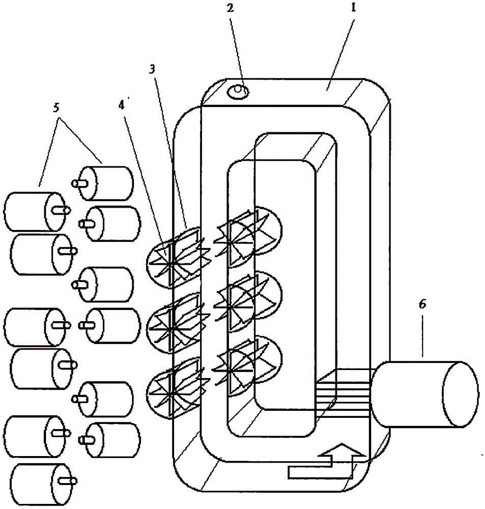
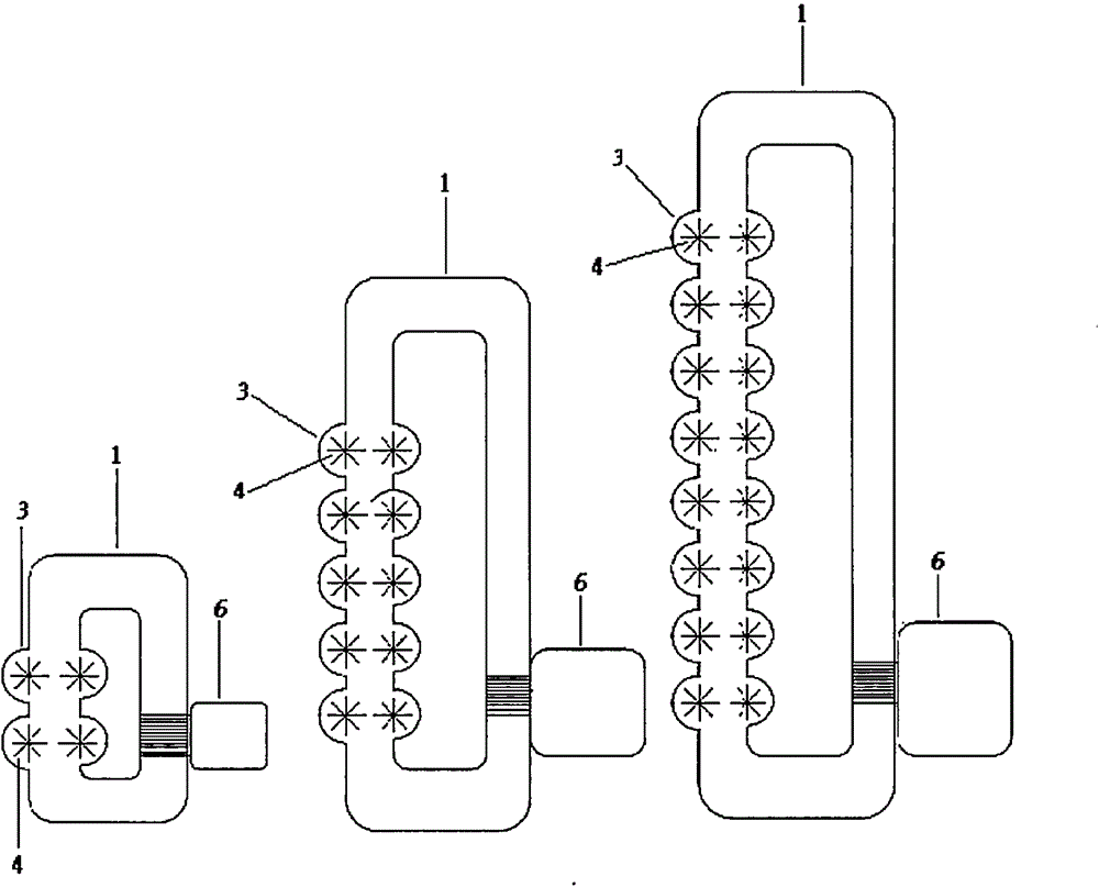
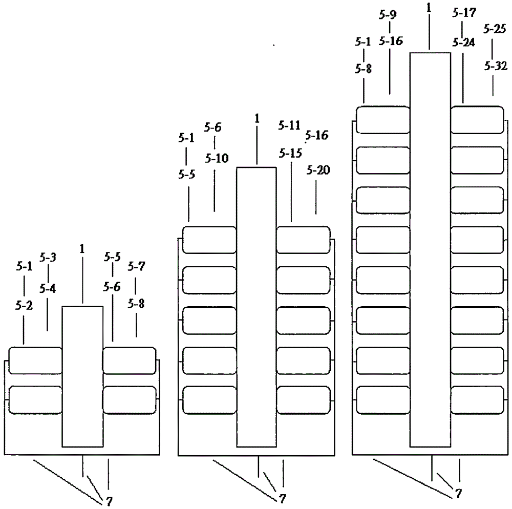
[0014] 【1】Please refer to Figure 4 and Figure 5 As shown, it illustrates an example of the combined pressurized circulation hydroelectric power generation device of the present invention that can be implemented in AC power generation. In this example, three multi-generator combination devices are assembled into a small-scale power generation facility that operates together. In this example, each device in the circulating tank ( Figure 4 1-1 to 1-3) on the two walls of one side, respectively set 8 semicircular protruding devices ( Figure 4 3-1 to 3-48), and install an impeller ( Figure 4 4-1 to 4-48), and install a generator at both ends of the impeller on the outer wall of the circulating water tank ( Figure 5 Among them, 5-1 to 5-96), a water pump is installed on the other side of the circulating water tank ( Figure 4 6-1 to 6-3), when the circulating water tanks are filled with water, cover the water tank covers with air holes, and start the water pumps with exter...


PUM


Abstract

A combined pressurized circulating hydroelectric unit comprises a circulating water tank, one or more impellers, generators and a water pump, wherein the one or more impellers are mounted on at least one tank wall edge of one side of the circulating water tank and can be mounted on the single edge as well as be mounted oppositely on two edges; each impeller mounting position of the circulating water tank adopts an outward bulging half-round structure; one or more impellers can be mounted, one generator is connected with one or two ends of each impeller; the water pump is mounted on the other side of the circulating water tank; after the circulating water tank is filled with water, a water tank cover comprising an air hole covers the circulating water tank, the water pump is started up through external electricity to drive the water in the water tank to flow continuously and circularly, the sufficient flow pressure is provided to drive the multiple impellers to rotate continuously, rotation of each impeller drives each connected generator to start continuous generation, at the moment, the external electricity for starting up the water pump is disconnected, part of the electricity generated by the device is supplied for long-term operation of the water pump instead, and the majority of the electricity generated by the device is output, so that the continuous, sable and efficient electricity generation and supply effects can be realized. Descriptions of appended drawing marks are as follows: 1-the circulating water tank, 2-the water tank cover comprising the air hole, 3-the half-round bulging structure of the circulating water tank wall edge, 4- the impeller, 5-the generator, and 6-the water pump.

Description

[0001] 【English invention name】Combinable pressurized circulating hydroelectric unit 【Technical field】 [0002] [1] The present invention relates to a combined pressurized circulation hydroelectric power generation device composed of a circulating water tank, an impeller, a generator, and a water pump. [0003] 【2】Hydroelectric power generation uses the kinetic energy of water flow to drive the generator to rotate to generate electricity. Based on this basic principle, the present invention integrates water, rotating impellers, generators, and water pumps and places them on and in a circulating water tank. Please refer to Figure 1 As shown, the water in the water tank is driven by the water pump to form a circulating water flow. The water flow continues to drive the impeller to rotate, and the impeller rotates to drive the connected generator to run and generate electricity. The connection between the impeller and the generator depends on the speed of rotation. It can be direc...

Claims


Application Information

Patent Timeline
IPC IPC(8): F03B13/00F03B11/00
CPCY02E10/226Y02E10/20
Inventor 杨得中
Owner 刘蓓嘉
Why Eureka
Try Eureka