Parking device for hydraulic drive device

A driving device and parking technology, which is applied in the direction of fluid pressure actuators, servo motors, mechanical equipment, etc., can solve the problems of casualties, safety hazards, back slipping, etc., and achieve good safety performance, simple results, and easy operation Effect

Active Publication Date: 2014-09-24
XIANGTAN HENGXIN IND
View PDF8 Cites 0 Cited by
  • Summary
  • Abstract
  • Description
  • Claims
  • Application Information

AI Technical Summary

Problems solved by technology

[0002] Due to the stable performance of hydraulic drive, it is widely used. Many drive devices adopt hydraulic drive mode. Hydraulic drive devices generally adopt the method of installing brakes on the shaft of the reducer and the side of the driving wheel to realize the op

Method used


Image

  • Parking device for hydraulic drive device

Examples


Example Embodiment

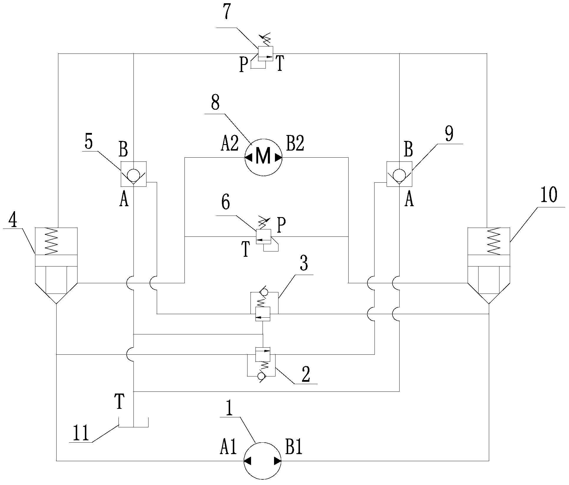
[0007] Such as figure 1 As shown, a parking device of a hydraulic drive device includes a hydraulic pump 1, a port A one-way sequence valve 2, a port B one-way sequence valve 3, a port A logic valve 4, a port B hydraulic control check valve 5, and a hydraulic motor Relief valve 6, logic valve control oil port relief valve 7, hydraulic motor 8, A port hydraulic control check valve 9, B port logic valve 10, oil tank 11, characterized by: A1 port and A port of hydraulic pump 1 The oil inlet of logic valve 4 is connected to the oil inlet of A-port one-way sequence valve 2, and the oil outlet of A-port one-way sequence valve 2 is connected to the control port of A-port hydraulic control check valve 9. The A port of the control check valve 9 is connected to the fuel tank 11, and the B port of the A port hydraulic control check valve 9 is connected to the control oil port of the B port logic valve 10 and the T port of the logic valve control oil port overflow valve 7. The B port of t...


PUM


Abstract

The invention discloses a parking device for a hydraulic drive device. The parking device comprises a hydraulic pump, an A-port one-way sequence valve, a B-port one-way sequence valve, an A-port logical valve, a B-port hydraulic control one-way valve, a hydraulic motor overflow valve, a logical valve control port overflow valve, a hydraulic motor, an A-port hydraulic control one-way valve, a B-port logical valve and an oil tank. The parking device has the following technical advantages that the oil way non-obstruction condition of the hydraulic motor is controlled through the overflow valves, so that the operation condition of the hydraulic motor is controlled, the parking function of the hydraulic motor is achieved, the backward sliding phenomenon caused by the fact that starting time of a brake can not be easily controlled is effectively avoided, and the problem that a person riding device is overhead and slides backwards when a load is started is solved; when unforeseen circumstances occur, the hydraulic motor is stopped so that the braking function can be achieved; the parking device is simple in structure, easy to operate and good in safety.

Description

technical field [0001] The invention relates to a hydraulic drive device. Background technique [0002] Due to the stable performance of hydraulic drive, it is widely used. Many drive devices adopt hydraulic drive mode. Hydraulic drive devices generally adopt the method of installing brakes on the shaft of the reducer and the side of the driving wheel to realize the operation and operation of the hydraulic drive device. However, when this braking method is used, it is difficult to control the opening time of the brake, which often leads to the phenomenon of slipping behind. The occurrence of casualty accidents has certain potential safety hazards. Contents of the invention [0003] The purpose of the present invention is to provide a hydraulic drive device parking device. [0004] The technical solution of the present invention is a parking device for a hydraulic drive device, including a hydraulic pump, a one-way sequence valve at port A, a one-way sequence valve at por...

Claims


Application Information

Patent Timeline
IPC IPC(8): F15B11/08
Inventor 肖公平肖连平陈林
Owner XIANGTAN HENGXIN IND
Why Eureka
Try Eureka