
Buckle type connection structure of contactor

A connection structure and snap-on technology, applied in relays, electromagnetic relays, electromagnetic relay details and other directions, can solve the problems of increasing the cost of screws, difficult to automate assembly, and high costs, achieving simple mold structure design, saving mold costs, Easy core pulling effect

Active Publication Date: 2014-09-24
XIAMEN HONGFA ELECTRICAL SAFETY & CONTROLS CO LTD
View PDF4 Cites 5 Cited by
  • Summary
  • Abstract
  • Description
  • Claims
  • Application Information

AI Technical Summary

Problems solved by technology

The defect of the contactor assembly structure is:
[0003] 1. Since there is no fixation between the coil bobbin and the body, the coil bobbin is easy to fall during automatic assembly, and it is difficult to realize automatic assembly
[0004] 2. The body and the base are locked by screws, and the locking of the screws needs to be done manually, which makes it difficult to realize automatic assembly
[0005] 3. Use screws to lock the body and the base, increasing the cost of using screws, making the cost relatively high

Method used


Image

  • Buckle type connection structure of contactor
  • Buckle type connection structure of contactor
  • Buckle type connection structure of contactor

Examples


Embodiment Construction

[0032] The present invention will be described in detail below in conjunction with the accompanying drawings and specific embodiments.

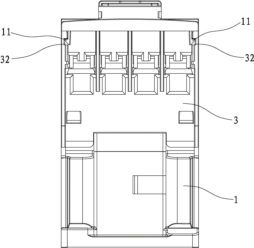
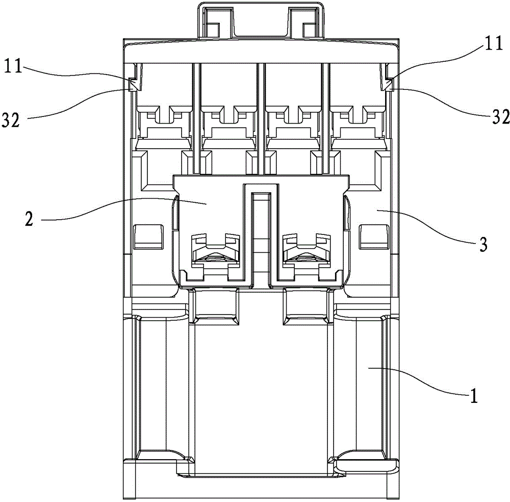
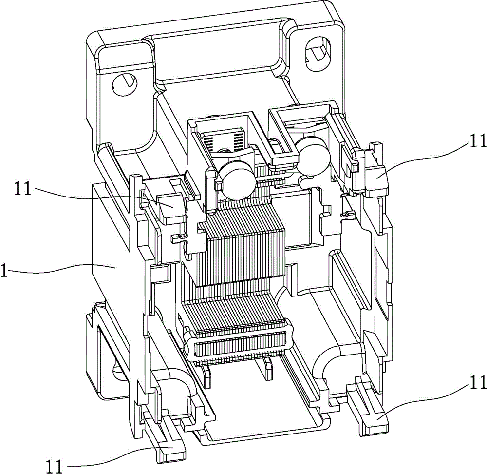
[0033] refer to Figure 1 to Figure 8 As shown, a snap-fit ​​connection structure of a contactor disclosed by the present invention includes a base 1, a coil frame 2 and a body 3; an accommodation cavity 30 for installing contacts is formed on the body 3, and the accommodation cavity 30 The room is separated by side panels 31, such as Figure 3c shown.

[0034] like Figure 7 and Figure 8 As shown, the coil bobbin 2 and the body shell 3 are connected through the first buckle 4, as Figure 4 and Figure 5 shown, combined with Figure 3b and Figure 3c As shown, the first buckle 4 is connected to protrude and extend on the central side plate 31 of the body shell 3 to form a buckle 311, the central side plate 31 is located on the axial center line of the body shell 3, and at the end The part forms a buckle 311, correspondingly, as Fig...


PUM


Abstract

The invention discloses a buckle type connection structure of a contactor. The buckle type connection structure comprises a shell and a coil frame. Containing cavities used for mounting contacts are formed in the shell and are separated by side plates. The buckle type connection structure is characterized in that the coil frame and the shell are connected through a first buckle, the first buckle protrudes and extends on the center side plate of the shell to be a buckle, the center side plate is on the axial center line of the shell, correspondingly, a limiting groove which is matched with the center side plate is formed on the coil frame, the coil frame is inserted into the shell, the center side plate passes through the limiting groove, the center side plate buckle is hooked on the coil frame at one side of the limiting groove, and the coil frame and the shell are connected. According to the buckle type connection structure, the contactor is suitable for automatic assembly, and the production cost is reduced.

Description

technical field [0001] The invention relates to the technical field of contactor assembly, in particular to a snap-fit ​​connection structure of a contactor. Background technique [0002] In the prior art, when the contactor is assembled, the coil bobbin is usually placed in the body first. At this time, the coil bobbin and the body are not fixed, and the coil bobbin is only placed in the cavity formed by the body, and then the body and the body The base is assembled by screw locking. The defect of the contactor assembly structure is: [0003] First, because there is no fixation between the coil bobbin and the body, the coil bobbin is easy to fall during automatic assembly, making it difficult to realize automatic assembly. [0004] Second, the body and the base are locked by screws, and the locking of the screws needs to be done manually, which makes it difficult to realize automatic assembly. [0005] Third, the use of screws to lock the body and the base increases the ...

Claims


Application Information

Patent Timeline
Patent Type & Authority Applications(China)
IPC IPC(8): H01H50/02
Inventor 田新疆夏昌慧
Owner XIAMEN HONGFA ELECTRICAL SAFETY & CONTROLS CO LTD
Learn More