Small all-metal slow wave device

An all-metal and metal technology, applied in the field of sub-wavelength small all-metal slow-wave devices, can solve the problems of low interaction efficiency of electron injection channels, improve output power and interaction efficiency, high breakdown voltage, and facilitate heat dissipation and the effect

Active Publication Date: 2014-09-24
UNIV OF ELECTRONICS SCI & TECH OF CHINA
View PDF10 Cites 15 Cited by
  • Summary
  • Abstract
  • Description
  • Claims
  • Application Information

AI Technical Summary

Benefits of technology

This patented technology uses a special type of material called metallic helix or spiraling wires inside a circle sheath. These materials have specific properties such as being able to absorb waves without generating unwanted signals like radioactive rays. They can be used alone or together to enhance certain aspects of lightwave devices' performance. By placing these components within this space around the entirety of one side of the core, they eliminate interference from other sources of radiation. Additionally, there is no longer any magnetic fields created during operation due to their symmetry design, which further improves the overall effectiveness of the device. Overall, this new method provides technical benefits over existing methods.

Problems solved by technology

This patents discusses different ways for improving the performance and efficiency at reducing the sizes of compact and efficient vacuumspace traveling wavelength tubular transistors called travelling wave tubings. These techniques aimed towards enhancing their ability to efficiently transmit signals without being bulky and heavyweight. They were developed through researchers' efforts over decades ago when studying these technical feations related to this new technique.

Method used


Image

  • Small all-metal slow wave device
  • Small all-metal slow wave device
  • Small all-metal slow wave device

Examples


Embodiment Construction

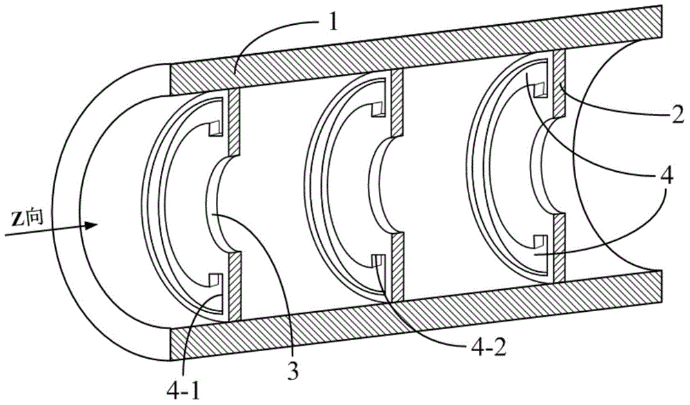
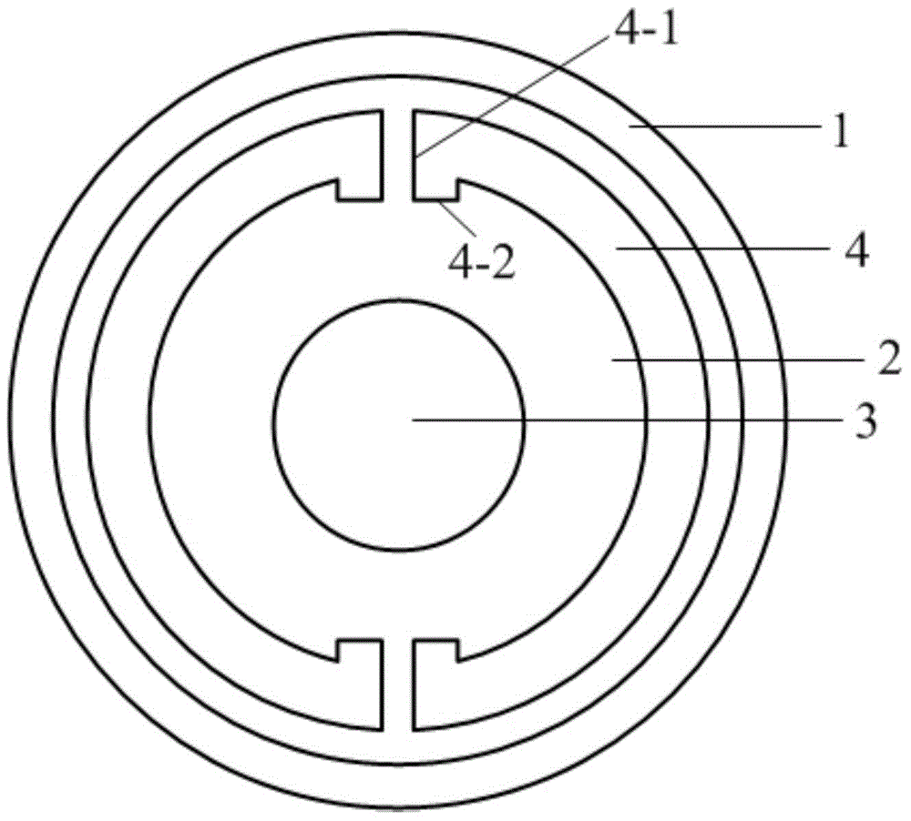
[0018] This implementation mode takes a miniaturized all-metal slow-wave device with an operating frequency range of 2.45-2.50 GHz as an example:

[0019]According to the guide wavelength of the guided electromagnetic wave working at the center frequency of 2.475 GHz is 85 mm, the free space wavelength is 110 mm; in this embodiment: the inner diameter of the cylindrical metal waveguide 1 is Φ40 mm, and the wall thickness is 5 mm. There are 24 in this embodiment The ring-type metal electric resonator 2, the center distance of each adjacent resonator is 30mm; the outer diameter of the ring-type metal electric resonator 2 is also Φ40mm, and the thickness of the piece is 1.2mm; the electron beam channel located in the center 3 Diameter Φ12mm; The outer ring surface radius R18mm and the inner ring surface radius R15mm (that is, the inner-outer ring surface The distance between the bottom surface of the cylindrical hole at both ends of each circular hole is 4-2 and the width is 3mm,...


PUM

PropertyMeasurementUnit
Thicknessaaaaaaaaaa

Abstract

The invention discloses a small all-metal slow wave device for a traveling wave tube or backward wave tube which works at a centimeter wave band or a millimeter wave band in the technical field of vacuum electronics. The small all-metal slow wave device comprises a cylindrical metallic wave conductor and annular sheet type metallic electric resonance pieces arranged inside the wave conductor at intervals, wherein the inner diameter of the cylindrical metallic wave conductor is not larger than one third of the free space wavelength of an electromagnetic wave working at a center frequency, an electron beam channel is formed in the middle of each annular sheet type metallic electric resonance piece, and two auricle-shaped through holes are symmetrically formed in the annular sheet body of each resonance piece. Due to the fact that the two auricle-shaped through holes generating electric resonance are symmetrically formed in the annular sheet body of each resonance piece, electromagnetism intercoupling is effectively eliminated, and only the electric resonance generated by electric dipoles exists. Taking a slow wave device working at the S waveband as an example, the cross section of the all-metal slow wave device is only 35%-50% that of a traditional coupled cavity traveling wave tube. Thus, the all-metal slow wave device has the advantages of being small in size, simple in structure, high in power capacity, output power and interaction efficiency, capable of being produced in an industrialized mode easily and the like.

Description


Claims


Application Information

Patent Timeline
Owner UNIV OF ELECTRONICS SCI & TECH OF CHINA
Why Eureka
Try Eureka