
Pin-shaped array antenna automatic pitching device

A technology for array antennas and pitching devices, which is applied in the directions of antennas, antenna arrays, electrical components, etc., can solve the problems of difficulty in ensuring the same pitch angle of the three antennas, large installation space, and large overall mass, so as to reduce the overall mass and reduce installation The effect of consistent space and pitch angle

Inactive Publication Date: 2016-08-03
NANHUA UNIV
View PDF4 Cites 0 Cited by
  • Summary
  • Abstract
  • Description
  • Claims
  • Application Information

AI Technical Summary

Problems solved by technology

[0002] At present, the installation method of the zigzag array antenna carried by the mobile platform is a spiral self-locking method. The zigzag array antenna is installed on the pitching device. The adjustment of the antenna pitch angle needs to be manually operated, and it is difficult to ensure three The pitch angle of the antenna is the same
Secondly, the pitching device of the existing pin-shaped array antenna mostly adopts a mechanical reducer, which has a large installation space and a large overall mass

Method used


Image

  • Pin-shaped array antenna automatic pitching device
  • Pin-shaped array antenna automatic pitching device
  • Pin-shaped array antenna automatic pitching device

Examples


Embodiment Construction

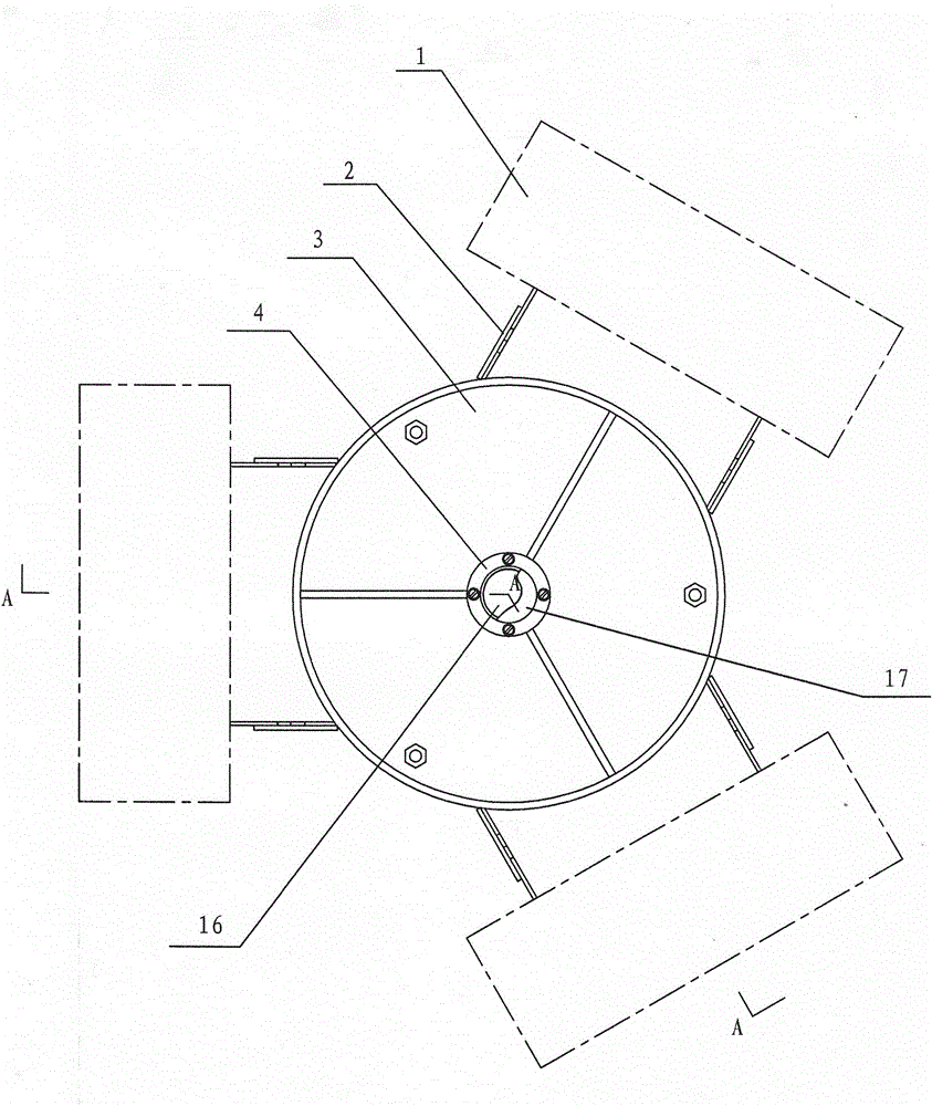
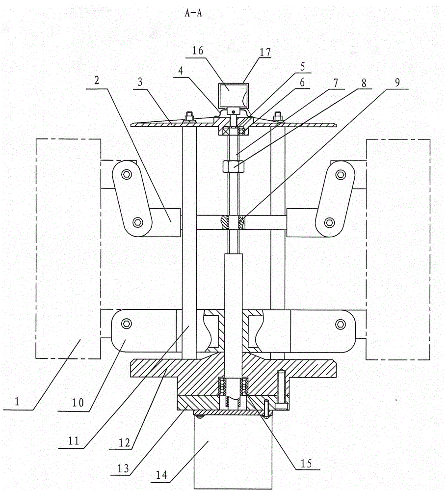
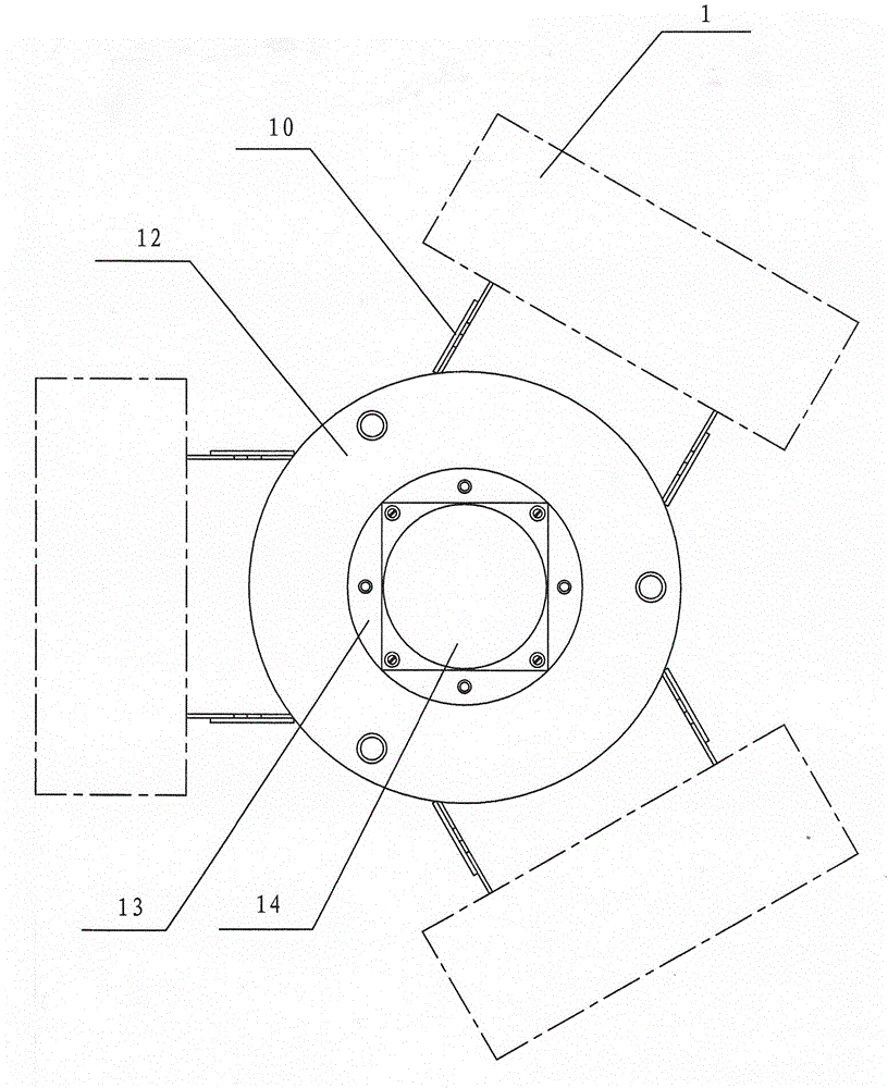
[0020] The technical solution of the present invention is: an automatic pitching device for an array antenna in the shape of a character, including an upper hinge bracket 2, an upper support plate 3, a protective cover 4, a bearing retaining ring 5, a deep groove ball bearing 6, a transmission shaft 7, a positioning Nut 8, ball 9, lower hinge bracket 10, column 11, lower support plate 12, bearing briquetting block 13, DC motor 14, angular contact bearing 15, rotary encoder 16 and rainproof cover 17.

[0021] Described upper hinge support 2 is made up of support 2-1, hinge frame 2-2 and hinge plate 2-3, and three support rods on the support 2-1 are 120 ° distribution, and the central part of support 2-1 is provided with Nut seat 2-4, nut seat 2-4 is fixed on the support 2-1 by welding, hinge plate 2-3 is installed on the side plate at hinge frame 2-2 two ends by hinge screw rod and nut, hinge plate 2-3 can Swing around the hinge screw, three hinge frames 2-2 are respectively we...


PUM


Abstract

An automatic pitching device for a character-shaped array antenna. The three columns in the device are welded on the lower support plate at 120°, two angular contact bearings are installed in the bearing mounting holes on the lower support plate, and the bearing pressing block is fixed on the lower support plate. At the bottom of the seat plate, the DC motor is fixed on the bearing pressing block, and one end of the transmission shaft passes through the angular contact bearing and is connected with the power output shaft of the DC motor. The lower hinge bracket is set on the transmission shaft, the upper hinge bracket is set on the screw part of the transmission shaft, the positioning nut is installed on the screw rod of the transmission shaft, and the deep groove ball bearing is installed in the bearing installation hole on the upper support plate. The upper support plate is fixed on the column, the protective cover is fixed on the upper support plate, and the other end of the transmission shaft passes through the inner hole of the deep groove ball bearing and is connected with the rotary encoder arranged on the protective cover. The bearing retaining ring is installed on the transmission shaft, and is between the bottom of the bearing mounting hole of the upper support plate and the inner ring of the deep groove ball bearing.

Description

technical field [0001] The invention relates to a pitching device for a character-shaped array antenna, in particular to an automatic pitching device for a character-shaped array antenna carried by a mobile platform and capable of automatically adjusting the pitch angle. Background technique [0002] At present, the installation method of the zigzag array antenna carried by the mobile platform is a spiral self-locking method. The zigzag array antenna is installed on the pitching device. The adjustment of the antenna pitch angle needs to be manually operated, and it is difficult to ensure three The pitch angles of the antennas are the same. Secondly, the pitching device of the existing pin-shaped array antenna mostly adopts a mechanical reducer, which has a large installation space and a large overall mass. Contents of the invention [0003] The purpose of the present invention is to overcome the above-mentioned deficiencies of the prior art and provide an automatic pitchi...

Claims


Application Information

Patent Timeline
Patent Type & Authority Patents(China)
IPC IPC(8): H01Q3/06H01Q21/00
Inventor 周炬苏金英李胜
Owner NANHUA UNIV
Learn More