
Arc spring and damper device

A shock absorber and arc technology, applied in the field of arc springs and shock absorber devices, can solve problems such as torque exceeding the limit, and achieve the effect of uniform torque

Active Publication Date: 2014-09-24
AISIN AW INDUSTRIES CO LTD
View PDF6 Cites 2 Cited by
  • Summary
  • Abstract
  • Description
  • Claims
  • Application Information

AI Technical Summary

Problems solved by technology

Therefore, the torsional force of the coil member constituting the inner peripheral portion of the arc spring may exceed the limit.

Method used


Image

  • Arc spring and damper device
  • Arc spring and damper device
  • Arc spring and damper device

Examples


Embodiment Construction

[0047] now refer to Figure 5(a) - Figure 17 A specific embodiment of the arc spring and shock absorber device of the present invention will be described.

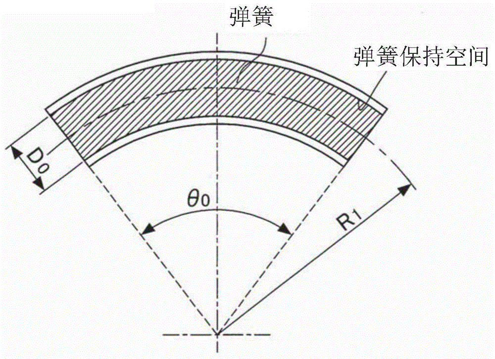
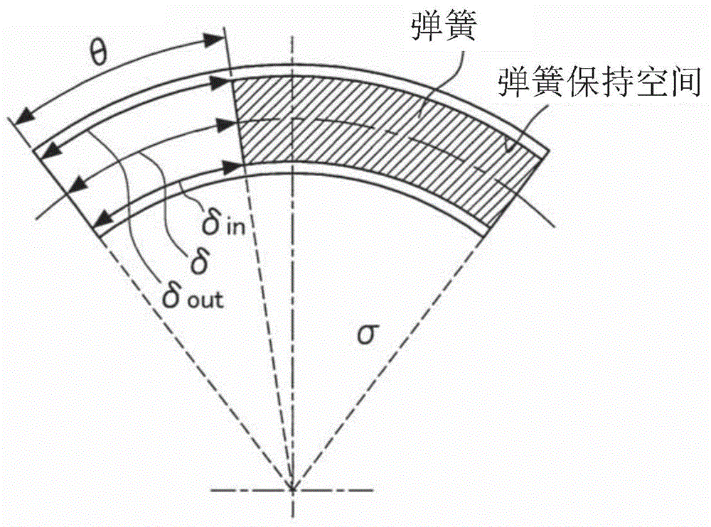
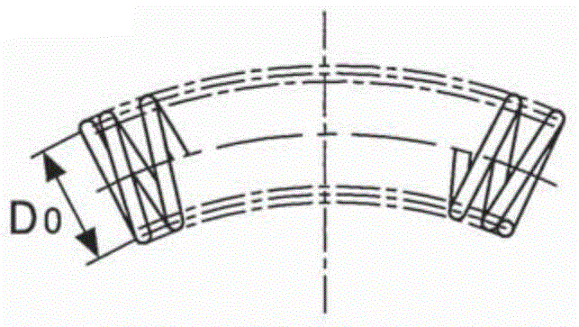
[0048] Figure 5(a) shows the arc spring 1 in a free state. FIG. 5( b ) shows the arc spring 2 held in the spring holding space 3 . As shown in Figure 5(a), the arc spring 1 has an average diameter D 0 , reference radius R a (i.e. predetermined radius of curvature) and free angle θ a . Conversely, the spring holding space 3 has a reference radius (installation diameter) R 1 (that is, the predetermined radius of curvature) and the installation angle θ 0 . That is, the arc spring 1 and the spring holding space 3 have different radii of curvature. After that, the arc spring is bent from the free state and held in the spring holding space 3 . The dotted line in Fig. 5(b) represents the arc spring 1 in the free state. The arc-shaped spring 2 held in the spring holding space 3 has a radius of curvature R 1 . When the ...


PUM


Abstract

A spring retaining space that retains therein an arc spring has a predetermined curvature radius and attachment angle. The arc spring is flexed and retained in the spring retaining space, and thus the curvature radius of the arc spring becomes small, while the attachment angle of the arc spring becomes larger than a free angle. Accordingly, torsion stress with a negative sign is applied to a coil member forming the inner circumferential portion of the arc spring.

Description

technical field [0001] The present invention relates to an arc spring and shock absorber arrangement. Background technique [0002] The spring is formed by a helically wound coil member. The spring is compressed by a load acting in the axial direction of the spring. In the case of straight cylindrical springs, the magnitude of torsion of the coil member resulting from compression of the spring is uniform. However, in the case of curved arc springs, the degree of twisting of the coil member due to compression of the arc springs is non-uniform. In the latter, the stroke magnitude of the outer peripheral portion of the arc spring is larger than the stroke magnitude of the inner peripheral portion of the arc spring. Therefore, the torsional force and deformation amount received by the coil member forming the inner peripheral portion of the arc spring are large. That is, the stroke magnitude of the arc spring outer peripheral portion depends on the deformation amount of the c...

Claims


Application Information

Patent Timeline
Patent Type & Authority Applications(China)
IPC IPC(8): F16F1/06F16D13/64F16F15/134
CPCF16F1/04F16H2045/0226F16D3/14F16F15/134F16D13/58F16F15/12F16F15/1232
Inventor 田中克典关秀基
Owner AISIN AW INDUSTRIES CO LTD
Learn More