
Glue mixing accelerator

An accelerator and glue mixing technology, applied in mixers, mixing methods, liquid and solid mixing, etc., can solve the problems of high glue supply pressure, easy blockage of glue guns, and small glue output, so as to improve flow rate and increase output. The effect of improving glue flow rate and service life

Active Publication Date: 2014-10-01
天津南玻节能玻璃有限公司
View PDF7 Cites 5 Cited by
  • Summary
  • Abstract
  • Description
  • Claims
  • Application Information

AI Technical Summary

Problems solved by technology

This passive glue mixing method has the following disadvantages: the glue mixing ratio is not stable, and the standard volume ratio of A and B glue cannot be completely and stably mixed, resulting in unstable quality of the final packaged insulating glass; the flow rate of the glue is low, and the amount of glue produced less, it is easy to block the glue gun, it needs to be interrupted frequently to clean the glue gun, and the glue gun is changed at least twice a day on average, which is inefficient; it needs a large glue supply pressure, which leads to the short life of each part; the requirements for the gear glue supply pump are extremely high High, the gear pump needs to be replaced frequently, and the maintenance cost is high

Method used


Image

  • Glue mixing accelerator
  • Glue mixing accelerator
  • Glue mixing accelerator

Examples


Embodiment Construction

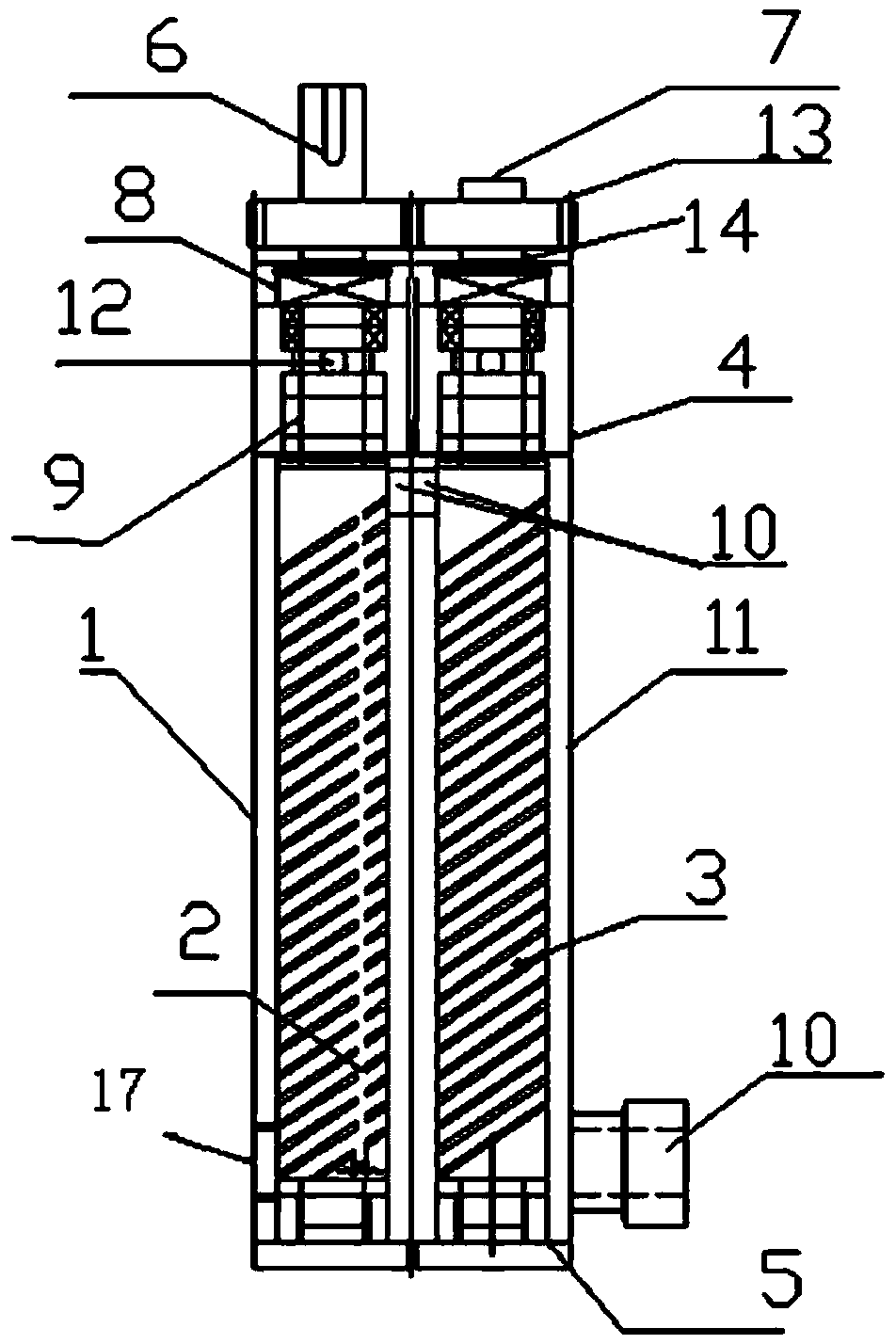
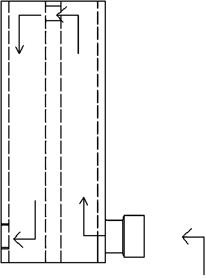
[0034] Such as Figures 1 to 3 As shown, the rubber mixing accelerator of the present invention includes two cavities arranged side by side, namely the first cavity 1 and the second cavity 11, and the upper and lower ends of the first cavity 1 and the second cavity 11 are respectively provided with upper and lower Cover 4 and base 5; the upper side of the first cavity 1 and the second cavity 11 are connected, the bottom side of the first cavity 1 is provided with an outlet 17, and the bottom side of the second cavity is provided with an inlet 10 , A, B component glue enters the second cavity 11 from the inlet at the same time according to the ratio, and then flows out from the outlet of the first cavity 1 to reach the working point;

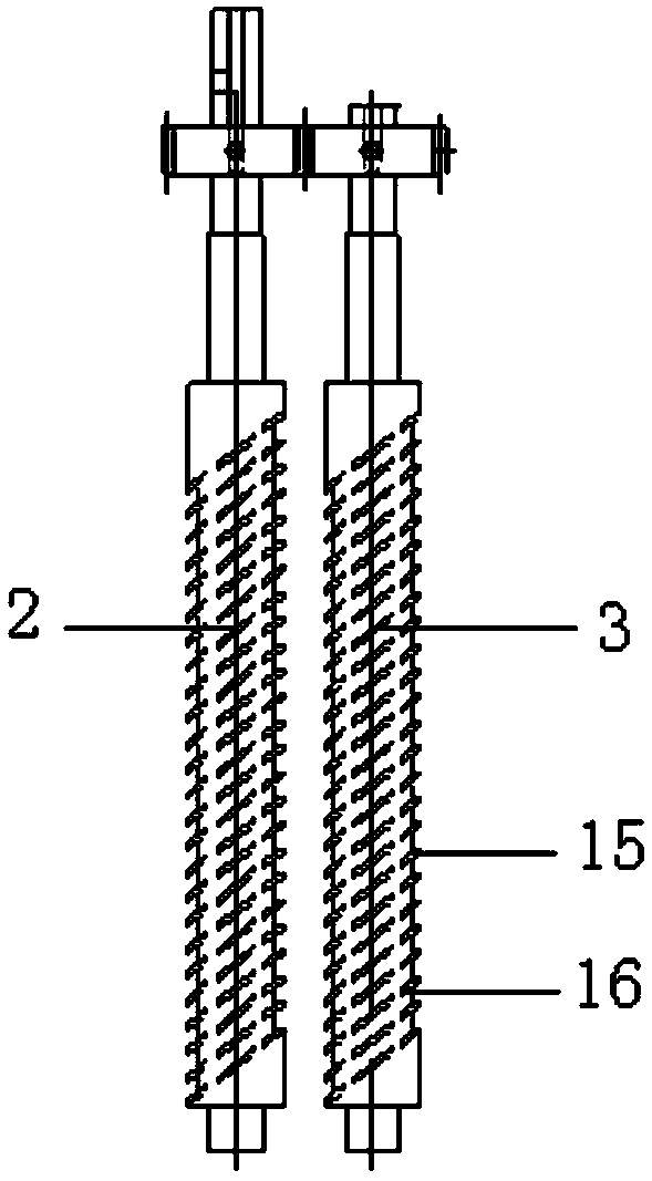
[0035] The first screw-type rubber mixing rod 2 and the second screw-type rubber mixing rod 3 are respectively installed in the first cavity 1 and the second cavity 11, the first screw-type rubber mixing rod 2 is driven by a driving device, and t...


PUM


Abstract

The invention relates to the technical field of glue mixing devices, and provides a glue mixing accelerator. The glue mixing accelerator comprises two cavity bodies arranged side by side, namely a first cavity body and a second cavity body; the first cavity body and the second cavity body are internally provided with a first screw-type glue mixing bar and a second screw-type glue mixing bar respectively; one of the first screw-type glue mixing bar and the second screw-type glue mixing bar is directly driven to rotate by a driving device, and the other one is transmitted to rotate by a transmission device. An original passive glue mixing mode of the glue mixing accelerator is changed into an active glue mixing mode, and the static glue mixing is changed into the active glue mixing; glue with a component A and glue with a component B in the cavity bodies are rotated and stirred in an acceleration manner by driving the two screw-type glue mixing bars to rotate, and can be stirred uniformly, and the flowing velocity of the glue is increased; the glue discharge flow is increased, so that the glue sealing efficiency is improved.

Description

technical field [0001] The invention belongs to the technical field of rubber mixing devices, in particular to a rubber mixing accelerator for making rubber mixing more uniform. Background technique [0002] With the automation requirements of modern production, all industries use high-strength, high-thixotropic, fast-curing, high-viscosity two-component adhesives, which are used after mixing the two components through the glue mixing device. [0003] In the prior art, the two-component glue mixing machines are all static glue mixing, such as the two-component adhesive mixing device described in the patent No. 200910224774.1 and the glue mixing device described in the patent No. 201210288526.5. The principle is to press the two kinds of glue into a mixing container in proportion to statically mix the glue. The above-mentioned passive glue mixing method is likely to cause problems such as uneven glue mixing and small glue output. [0004] At present, for the two-component g...

Claims


Application Information

Patent Timeline
Patent Type & Authority Applications(China)
IPC IPC(8): B01F7/24B01F3/14B01F23/57
Inventor 崔玉鹏胡克武张东林
Owner 天津南玻节能玻璃有限公司
Learn More