Multi-station punching device

A stamping device and multi-station technology, applied in the field of machinery, can solve the problems of reduced safety performance, low work efficiency, accidental injury to operators, etc., and achieve the effect of high automation and high work efficiency

Active Publication Date: 2014-10-01
NINGBO NEW GUANLIAN MOTOR ELECTRONICS
View PDF9 Cites 40 Cited by
  • Summary
  • Abstract
  • Description
  • Claims
  • Application Information

AI Technical Summary

Problems solved by technology

If such a structural design is not coordinated or moves too fast during the period, it may accidentally injure the operator's hand, reduce safety performance and lower work efficiency

Method used


Image

  • Multi-station punching device
  • Multi-station punching device
  • Multi-station punching device

Examples


Embodiment Construction

[0022] The following are specific embodiments of the present invention and in conjunction with the accompanying drawings, the technical solutions of the present invention are further described, but the present invention is not limited to these embodiments.

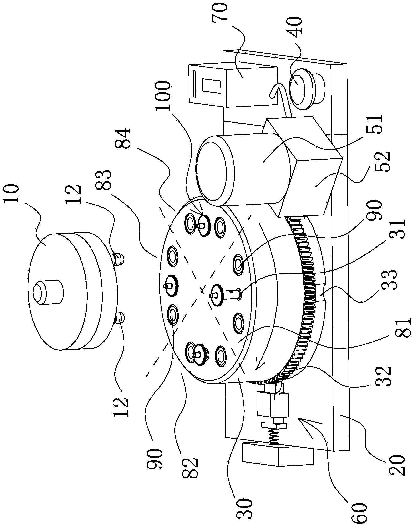
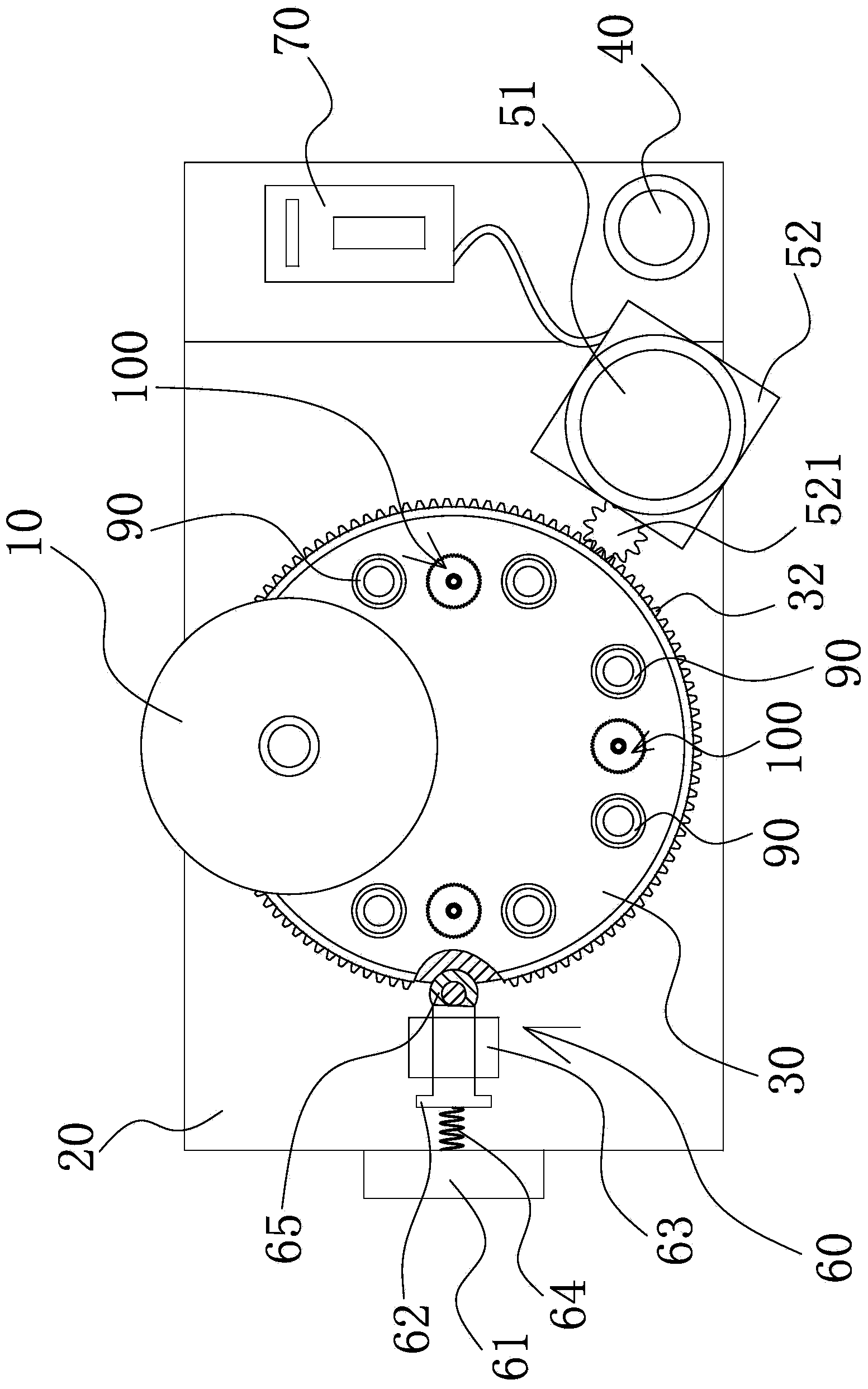
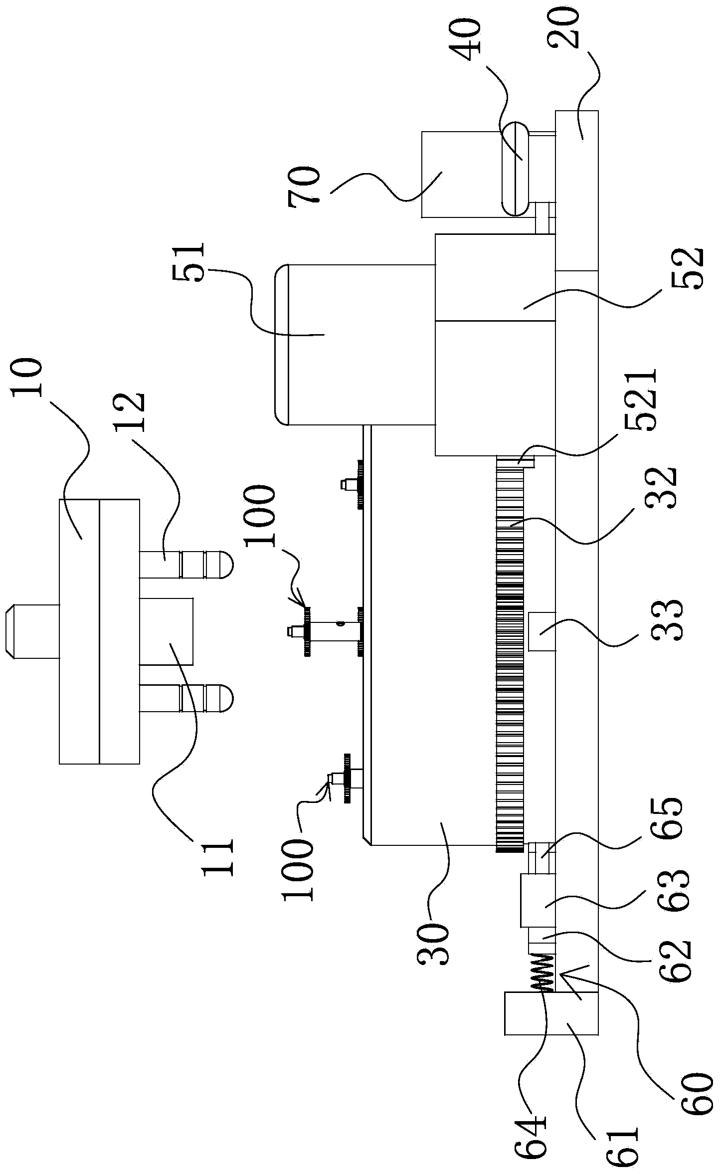
[0023] Such as Figure 1 to Figure 4 As shown, the multi-station stamping device includes an upper die 10 and a lower die base 20 arranged below the upper die 10 , a punch 11 is arranged at the middle part of the end face of the upper die 10 facing the lower die base 20 , and on the lower die base 20 A turntable 30 that matches the punch 11 is rotatably installed, and at least two die holes 31 for placing the product 100 are provided on the end face of the turntable 30 facing the upper die 10, and a control switch is provided on the lower die base 20 40 and the driving member 51 that can drive the turntable 30 to rotate. When the turntable 30 rotates, one of the die holes 31 is located below the upper die 10 and coaxially ...


PUM


Abstract

The invention provides a multi-station punching device and belongs to the field of mechanical technology. The multi-station punching device comprises an upper die and a lower die holder arranged under the upper die. The middle of the end surface of the upper die, which faces towards the lower die holder, is provided with a punch; the lower die holder is rotatably provided with a turntable matched with the punch; the end surface of the turntable, which faces towards the upper die, is provided with at least two die holes for placing products; the lower die holder is provided with a control switch and a driving unit for driving the turntable to rotate. When the turntable rotates, one of the die holes is positioned under the lower die and is coaxial with the punch, the other die holes are disposed on the circumference of the upper die, and the control switch, the driving unit and the upper die are electrically connected to form a closed circuit. The multi-station punching device has the advantages of being high in working efficiency, safe and reliable.

Description

technical field [0001] The invention belongs to the technical field of machinery and relates to a multi-station stamping device, in particular to a multi-station stamping device suitable for stamping motor accessories. Background technique [0002] In the prior art, some motor accessories need to be produced by punching two workpieces by a punching device. Most of the punching devices use ordinary single-station punching devices to punch products. The above-mentioned products refer to the combination of two workpieces that need to be punched for motor accessories. [0003] Existing single-station stamping devices generally include an upper die and a lower die matched with the upper die. The upper die has a punch, and the lower die is provided with a die hole located below the punch. The working process of the above-mentioned single-station stamping device is as follows: the product is directly placed in the die hole directly below the punch by the operator, and the operator...

Claims


Application Information

Patent Timeline
Patent Type & Authority Applications(China)
IPC IPC(8): B21D22/02B21D55/00B21D37/10
Inventor 任杨方岳云
Owner NINGBO NEW GUANLIAN MOTOR ELECTRONICS
Why Eureka
Try Eureka