Straight-ejection inclined core-pulling device for multiple parallel linked core blocks for injection mold

A technology of injection mold and straight top, which is applied in the field of oblique core-pulling devices, and can solve problems such as increased cost, high cost, and increased shape

Active Publication Date: 2014-10-01
宁波宇升模塑有限公司
View PDF4 Cites 8 Cited by
  • Summary
  • Abstract
  • Description
  • Claims
  • Application Information

AI Technical Summary

Problems solved by technology

[0003] For the oblique pulling demoulding of a single oblique core block, the prior art adopts a one-to-one method, that is, a set of oblique driving mechanism is set for one oblique core block to carry out oblique pulling and demoulding, and the oblique driving mechanism can adopt oblique The ejector rod is used for inclined jacking, or the oil cylinder is used for oblique pulling; however, for parallel multi-core block molds, the one-to-one method will make the mold structure extremely complicated, the shape will increase, and the cost will increase significantly. Therefore, the existing technology exists The problems and deficiencies of complex structure, large shape and high cost

Method used


Image

  • Straight-ejection inclined core-pulling device for multiple parallel linked core blocks for injection mold
  • Straight-ejection inclined core-pulling device for multiple parallel linked core blocks for injection mold
  • Straight-ejection inclined core-pulling device for multiple parallel linked core blocks for injection mold

Examples


Embodiment Construction

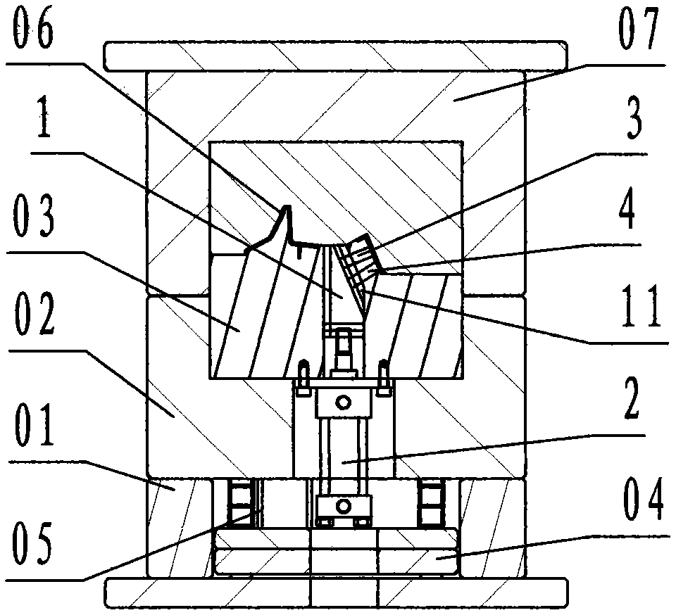
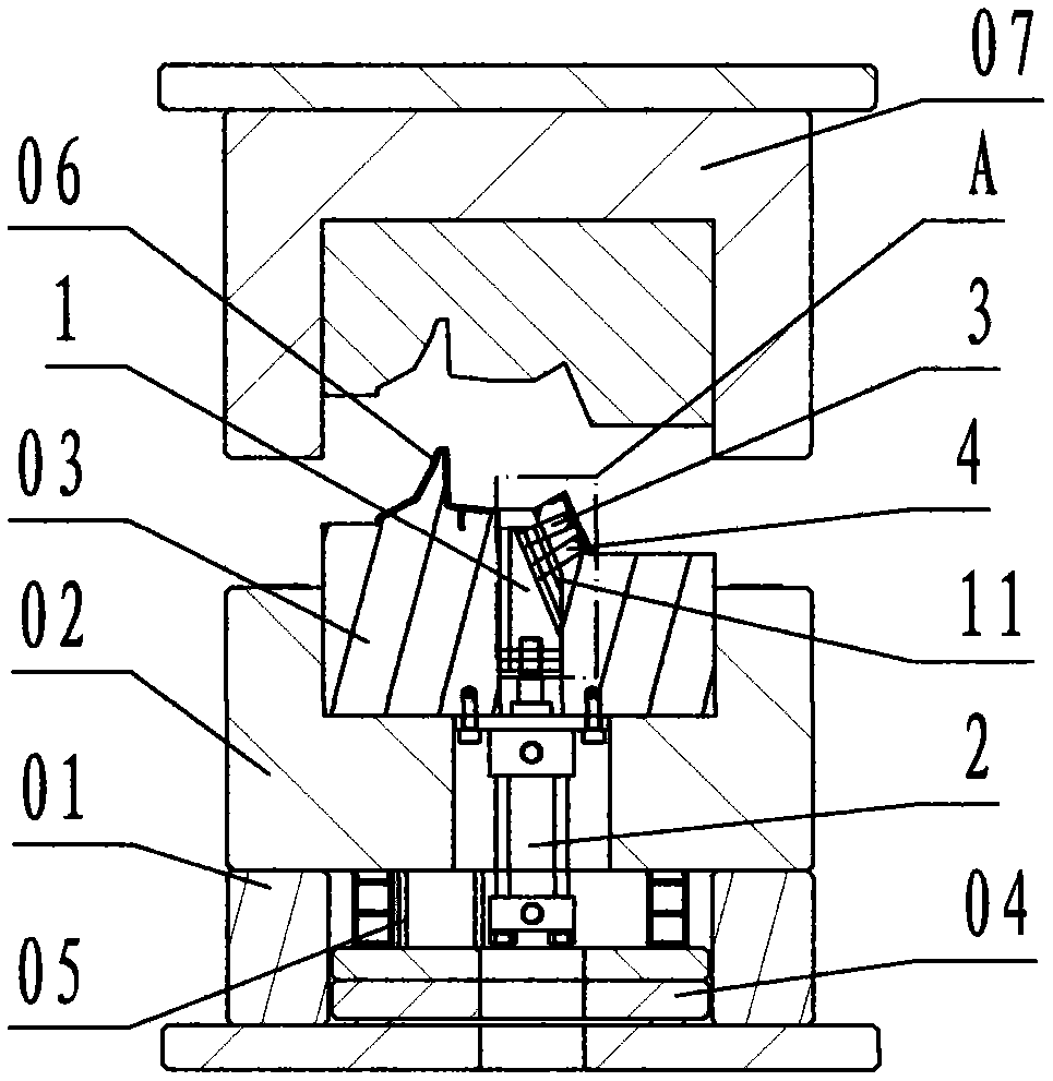
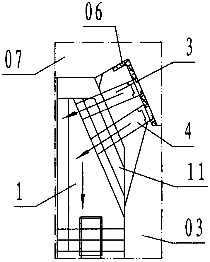
[0021] refer to Figure 1 ~ Figure 4 , a straight top slant pumping device for parallel multi-core block linkage of an injection mold according to the present invention, comprising a straight top slant rail slider 1, an oil cylinder 2, A slant core block 3, B slant core block 4, wherein: the The straight top ramp slider 1 is a wedge-shaped block-shaped steel member, and the right side of the straight top ramp slider 1 is provided with a protruding T-shaped track that is inclined from up to down to the right and is called a ramp slide 11;

[0022] The oil cylinder 2 is a hydraulically telescopic actuator composed of a cylinder body and a piston rod;

[0023] The A oblique core block 3 is a hexagonal block-shaped steel member, the cross section of the A oblique core block 3 is rectangular, and the right side of the A oblique core block 3 is provided with a molded product 06 inside hook The core-pulling profile of the structure, the left side of the A inclined core-pulling block...


PUM


Abstract

The invention discloses a straight-ejection inclined core-pulling device for multiple parallel linked core blocks for an injection mold. The device comprises a straight-ejection inclined rail sliding block (1), an oil cylinder (2), an inclined pulling core block A (3) and a inclined pulling core block B (4), wherein the right side of the straight-ejection core block-pulling sliding block is provided with a bevel sliding rail; the right sides of the inclined pulling core block A and the inclined pulling core block B are provided with core-pulling profiles, the left sides of the inclined pulling core block A and the inclined pulling core block B are provided with a sliding chute A and a sliding chute, respectively, and the pressure angles of the sliding chute A and the sliding chute B are different; the inclined pulling core block A and the inclined pulling core block B are parallel, have different inclined pulling angels and are respectively slidingly connected with the bevel sliding rail of the straight-ejection inclined rail sliding block through the sliding chute A and the sliding chute B; a cylinder body of the oil cylinder is fixedly and vertically connected with a movable mold support plate along an up-down direction, the lower surface of the straight-ejection inclined rail sliding block is fixedly connected with a piston rod of the oil cylinder; when the core-pulling is performed, the oil cylinder drives the straight-ejection inclined rail sliding block to vertically move downward, and the inclined pulling core block A and the inclined pulling core block B are respectively demolded from respective core-pulling axes synchronously. By adopting the technical scheme, the parallel multi-core block mold achieves the aim of simplifying structure, reducing the size and reducing cost.

Description

technical field [0001] The invention relates to an oblique core-pulling device for an injection mold, specifically refers to a parallel multi-core block linkage of an injection mold that synchronously pulls out a plurality of oblique core-pulling blocks that are parallel and have different core-pulling angles. Straight top inclined pumping device. Background technique [0002] Based on the needs of the structure of some injection molded products, multiple, side-by-side, oblique core-pulling blocks with different oblique drawing angles are required in the same position area of ​​the injection mold, referred to as parallel multi-core block molds; the so-called oblique drawing angle is oblique core-pulling The core-pulling movement direction line of the block, that is, the angle between the core-pulling axis and the opening and closing direction line of the injection mold; [0003] For the oblique pulling demoulding of a single oblique core block, the prior art adopts a one-to...

Claims


Application Information

Patent Timeline
Patent Type & Authority Applications(China)
IPC IPC(8): B29C45/33
CPCB29C45/33
Inventor 叶元建顾宏科
Owner 宁波宇升模塑有限公司
Why Eureka
Try Eureka