Detaching apparatus and detaching method

A technology of peeling device and starting position, applied in the direction of copying/marking method, transportation and packaging, printing, etc., can solve the problems of pattern damage, insufficient holding force, component drop, etc., and achieve a good peeling effect

Inactive Publication Date: 2014-10-01
DAINIPPON SCREEN MTG CO LTD
View PDF7 Cites 26 Cited by
  • Summary
  • Abstract
  • Description
  • Claims
  • Application Information

AI Technical Summary

Problems solved by technology

Such fluctuations in the speed of peeling cause damage to patterns and the like due to stress concentration.
[0005] In addition, there are problems such as that the amount of movement for separating the two members increases, thereby increasing the operating space, or the members are bent or cracked due to bending, and the members fall due to insufficient holding force.
These problems become more pronounced especially as the components to be stripped become larger

Method used


Image

  • Detaching apparatus and detaching method
  • Detaching apparatus and detaching method
  • Detaching apparatus and detaching method

Examples


Embodiment Construction

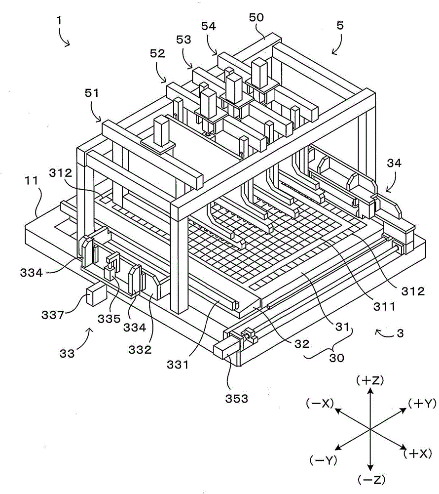
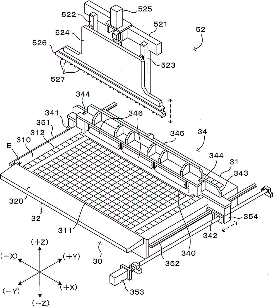
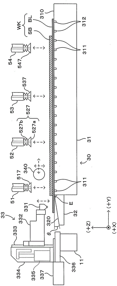
[0033] figure 1 It is a perspective view which shows one Embodiment of the peeling apparatus of this invention. In order to unify the directions in the following figures, such as figure 1 As shown in the lower right of , set the XYZ orthogonal coordinate axes. Here, the XY plane represents a horizontal plane, and the Z axis represents a vertical axis. More specifically, the +Z direction indicates a vertically upward direction.

[0034] This peeling device 1 is a device for peeling two plate-shaped objects carried in with their main surfaces in close contact with each other. For example, it is used in a part of the pattern forming process of forming a predetermined pattern on the surface of a substrate such as a glass substrate or a semiconductor substrate. More specifically, in this pattern forming process, the pattern forming material is uniformly applied on the surface of the blanket as a carrier for temporarily carrying the pattern to be transferred (coating process), a...


PUM


Abstract

The invention relates to a detaching apparatus and a detaching method. A plurality of attracting units (51-54) are configured in a detaching performing direction, namely a +Y direction. A first attracting unit (51) at a most upstream side attracts an end of a retained substrate (SB) for lifting. Furthermore through making a detaching roller (340) abut against the substrate (SB) and move in the detaching performing direction, thereby controlling detaching. When the detaching roller (340) passes through the position right below a second attracting unit (52) to a fourth attracting unit (54), the substrate after detaching is captured and lifted through making each attracting unit (52-54) descending, thereby making the attracting units which perform the function of detaching from the body successively move to the downstream side.

Description

technical field [0001] The present invention relates to a peeling device and a peeling method for peeling and separating two plate-shaped objects that are in close contact with each other. Background technique [0002] As a technique for forming a predetermined pattern or thin film on a plate-like body such as a glass substrate or a semiconductor substrate, there is a technique of converting a pattern or a thin film (hereinafter referred to as "pattern", etc.) printed on the substrate. In this technique, after transferring a pattern or the like from one to the other by bringing the two plate-shaped bodies into close contact, it is necessary to peel the two plate-shaped bodies without damaging the pattern. [0003] As a technique that can be used for this purpose, for example, Japanese Patent Application Laid-Open No. 2003-072123 discloses a technique of patterning color filters, circuit wiring, and the like of a liquid crystal display device on a recording medium. In this ...

Claims


Application Information

Patent Timeline
Patent Type & Authority Applications(China)
IPC IPC(8): B41F16/00B41M5/00
CPCB65H29/56B65H2301/51122B65H2701/1726
Inventor 上野美佳川越理史增市干雄上野博之
Owner DAINIPPON SCREEN MTG CO LTD
Why Eureka
Try Eureka