Winding mechanism

A technology of winding mechanism and winding wheel, which is applied in the field of cable storage devices, can solve the problems of unfavorable cable winding efficiency and labor intensity of operators, and achieve a good straightening effect and reduce the gap effect

Inactive Publication Date: 2014-10-01
SICHUAN TIANWEI ELECTRONICS
View PDF5 Cites 2 Cited by
  • Summary
  • Abstract
  • Description
  • Claims
  • Application Information

AI Technical Summary

Problems solved by technology

[0003] Aiming at the problems in the above-mentioned prior art that the operator manually applies pulling force to the cable to correct the above-mentioned deformation during the cable winding process, which is not conducive to the cable winding efficiency and the labor intensity of the operator, the present invention provides winding mechanism

Method used


Image

  • Winding mechanism
  • Winding mechanism

Examples


Embodiment 1

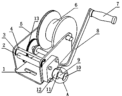
[0025] Such as figure 1 with figure 2 , A winding mechanism, including a frame 5 and a reel 6 arranged on the frame 5, the frame 5 is also provided with a reel brake for braking the reel 6 to rotate around its axis Mechanism and cable leveling mechanism;

[0026] The cable leveling mechanism includes a fixed rod 2 and a movable rod 4 which are arranged on the frame 5 and whose axes are parallel to each other, and the distance between the movable rod 4 and the fixed rod 2 is linearly adjustable;

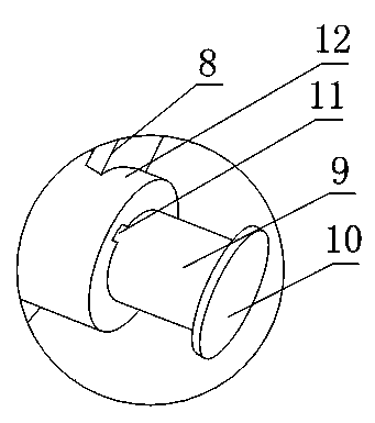
[0027] The reel brake mechanism includes a gear train 13 and a rocker 8. One end of the rocker 8 is fixed at the front end of the gear train 13, and the rear end of the gear train 13 meshes with the reel 6 in gear teeth. Series 13 is a reduction drive gear train;

[0028] The gear train 13 also includes a driving wheel rod 9, the gear at the front end of the gear train 13 is fixed on the driving wheel rod 9, the connecting end of the rocker 8 and the gear train 13 is also fixedly connecte...

Embodiment 2

[0031] This embodiment is further limited on the basis of embodiment 1, such as figure 1 with figure 2 In order to facilitate linear adjustment of the distance between the movable rod 4 and the fixed rod 2, the frame 5 includes a bottom plate and two side plates respectively fixed on different sides of the bottom plate, and each side plate is provided with an arc hole 3. Both ends of the movable rod 4 are respectively located in an arc-shaped hole 3, and the movable rod 4 is fixedly connected with the frame 5 through a nut.

[0032] In order to facilitate the fixation of the frame 5 of the present invention, and to facilitate winding and winding, the bottom plate is also provided with at least two bottom plate bolt holes 1, and the bottom plate bolt holes 1 are waist-shaped holes. The adoption of the bottom plate bolt hole 1 as a waist-shaped hole is intended to reduce the requirement of the present invention for the dimensional accuracy of the connecting bolt of the mounting se...

Embodiment 3

[0035] This embodiment is further limited on the basis of embodiment 1, such as figure 1 with figure 2 , In order to prevent excessive friction damage to the outer layer of the cable when the cable passes through the gap between the fixed rod 2 and the movable rod 4, the fixed rod 2 and the movable rod 4 both include a rigid part and a sleeve provided on the inner side The wear-resistant part on the rigid part, the rigid part is metal, and the wear-resistant part is elastic rubber.


PUM


Abstract

The invention discloses a winding mechanism. The winding mechanism comprises a machine frame and a winding wheel, wherein the machine frame is provided with a winding wheel brake mechanism and a cable straightening mechanism, the cable straightening mechanism comprises a fixing rod and a moving rod, the distance between the fixing rod and the moving rod is linearly adjustable, the winding wheel brake mechanism comprises a gear train and a rocking bar, the gear train is a reduction drive gear train, the gear train further comprises a drive wheel rod, a gear at the front end of the gear train is fixed on the drive wheel rod, a sleeve is fixedly connected with the connection end of the rocking bar and the gear train, a through hole for the drive wheel rod to penetrate through is formed in the sleeve, a key groove is formed in the side face of the through hole, a key matched with the key groove in keying mode is arranged on the drive wheel rod, and the key is parallel to the axis of the drive wheel rod. The winding mechanism is simple in structure, and is high in winding and unwinding efficiency, automatically completes straightening and reshaping work of a cable and obtains good reshaping effects during the winding and unwinding process, and furthermore facilitates use life extension of the cable and safety of operating personnel.

Description

Technical field [0001] The invention relates to a cable storage device, in particular to a winding mechanism. Background technique [0002] In the prior art, power cables and communication cables are used in various fields. Cables that are laid out and need to be reused are usually stored by winding rollers. The main winding component of the winding roller is the winding wheel. The rotation of the wire wheel winds the cable around it in a loop shape to reduce the space occupied by the above-mentioned cable and facilitate storage and transportation. However, the cable is easy to bend when subjected to external force during use, and the bent part will be more and more deformed during the reuse of the cable, and the cable will break at the bent part over time. In the prior art, during the cable winding process, the operator manually applies a pulling force to the cable to correct the aforementioned deformation, which is not conducive to the efficiency of cable winding and the labor...

Claims


Application Information

Patent Timeline
IPC IPC(8): B65H75/34
Inventor 李继良蒋洪炎白辉
Owner SICHUAN TIANWEI ELECTRONICS
Why Eureka
Try Eureka