Oil inlet of common rail injector

A common rail fuel injector and fuel injector technology, which is applied in the directions of machines/engines, fuel injection devices, engine components, etc., can solve the problems of long control piston length, affecting the performance of fuel injectors, and easy instability, etc. Work stability, avoid work instability, reduce the effect of lateral impact force

Active Publication Date: 2014-10-01
CHINA FAW LIMITED WUXI FUEL INJECTIONEQUIP RES INST +1
View PDF5 Cites 2 Cited by
  • Summary
  • Abstract
  • Description
  • Claims
  • Application Information

AI Technical Summary

Problems solved by technology

Because the length of the control piston is relatively large, especially after the control piston and the needle valve are made into an integrated structure, it is easy to lose stabi

Method used


Image

  • Oil inlet of common rail injector
  • Oil inlet of common rail injector
  • Oil inlet of common rail injector

Examples


Embodiment Construction

[0017] The oil inlet structure of a common rail fuel injector in the present invention can refer to the attached Figure 1~4 description of

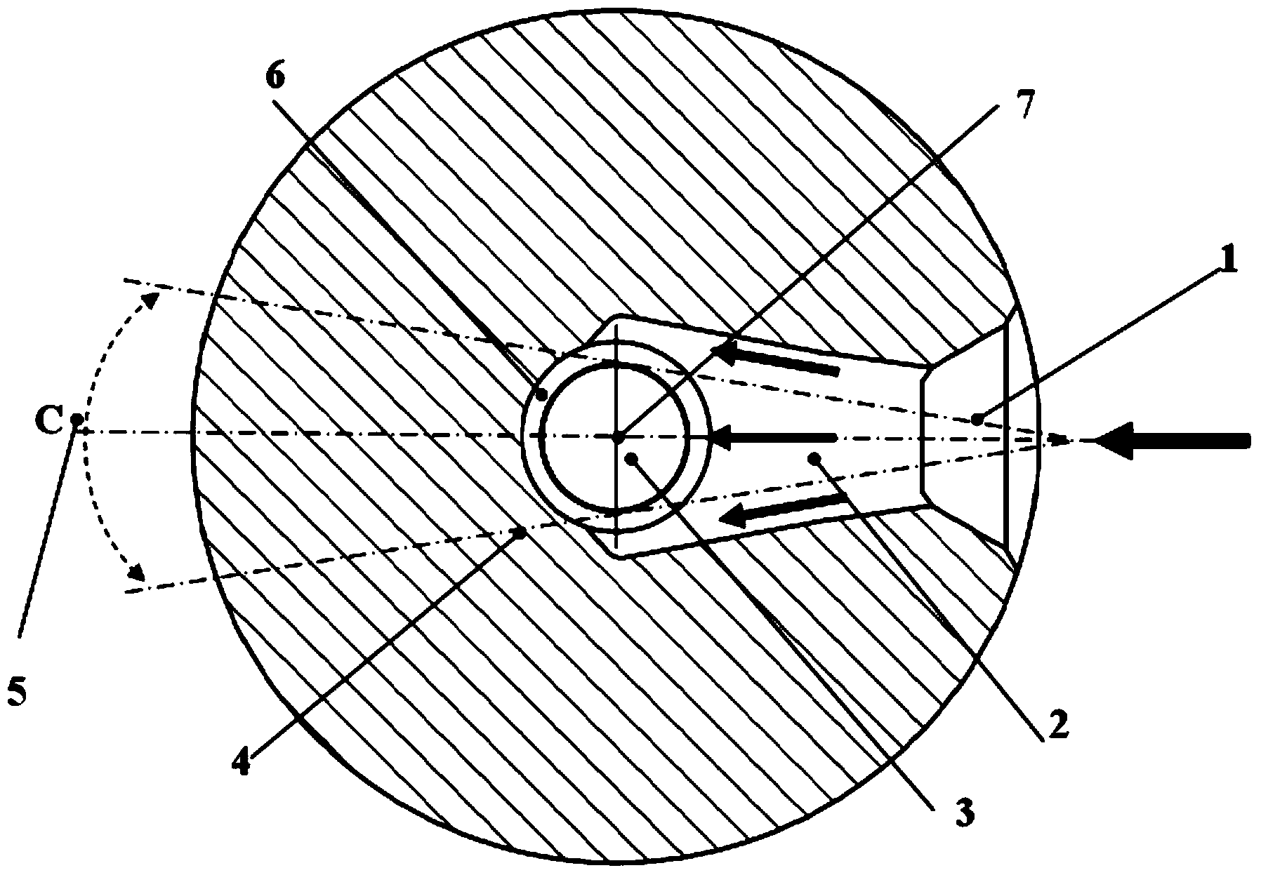
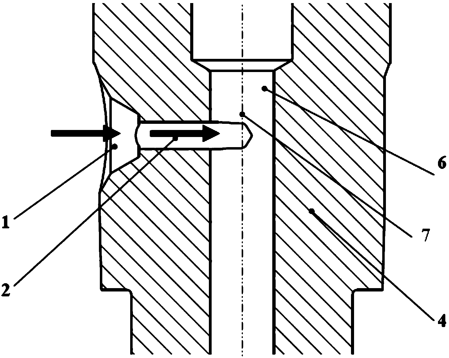
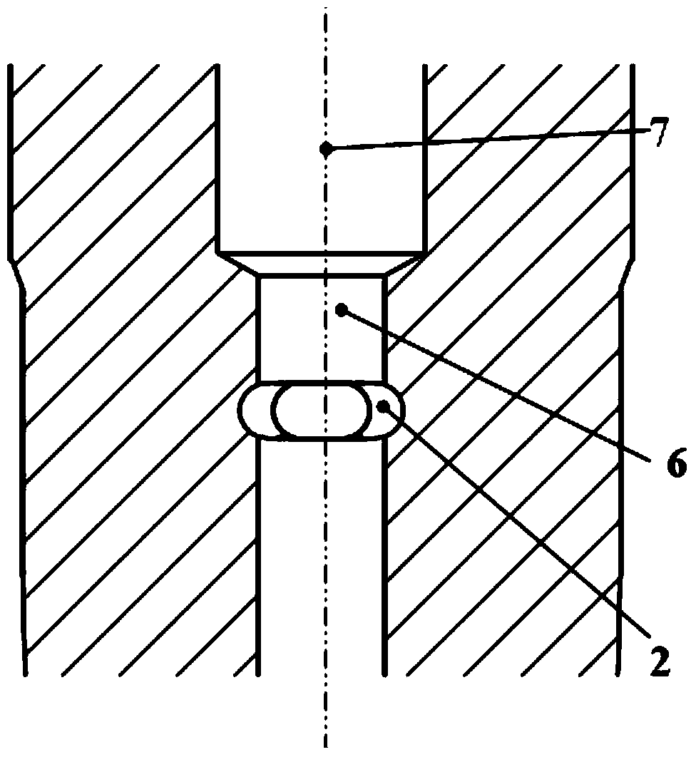
[0018] One kind of fuel injector oil inlet is the oil passage between the oil inlet horizontal chamber and the high pressure oil chamber 6 in the fuel injector. The oil inlet of the present invention is composed of two parts of oil passages. The oil passage a 1 located on the outermost side of the injector body 4 is tapered from the fuel flow direction, and the cross-sectional shape of the oil passage a 1 is circular. The oil passage a 1 is used to connect with the oil inlet transverse cavity, and the tapered tapered structure can ensure the sealing of high-pressure fuel at the connection.

[0019] The section shape of the fuel passage b 2 inside the injector body 4 is waist-shaped, which can make more fuel flow to both sides of the control piston 3 and reduce the fuel directly flowing to the control piston 3 from the front. At the sam...


PUM


Abstract

The invention discloses an oil inlet of a common rail injector. The oil inlet of the common rail injector is oil ways between an oil inlet horizontal cavity between the high-pressure oil cavity inside the injector and comprises an oil way a on the outermost side of an injector body, and an oil way b inside the injector body; the oil way a is connected with the oil inlet horizontal cavity of the injector, and the oil way b is connected with the high-pressure oil cavity inside the ejector; the oil way a is in the shape of a reducing cone in the fuel flowing direction, and the oil way is of an increasing structure in the direction perpendicular to the axis of the ejector body; the first section of the oil way a is used for connecting the oil inlet horizontal cavity to ensure sealing of high-pressure fuel; a kidney-shaped-hole structure of the oil way b enables more fuel to flow towards both sides of a control piston and reduces fuel directly flowing towards the control piston from the front surface; meanwhile, the increasing structure of the oil way b further enables the high-pressure fuel to flow towards both sides of the control piston and further avoids direct impact of the high-pressure fuel onto the control piston. Therefore, the oil inlet of the common rail ejector can reduce the lateral impact force born by the control piston, effectively avoid instability of the control piston and improve the working stability of the ejector.

Description

technical field [0001] The invention belongs to the field of fuel injection systems of internal combustion engines, and in particular relates to an oil inlet structure of a common rail fuel injector. Background technique [0002] As the injection pressure of the common rail system increases, the injector begins to adopt a non-static oil return design. Moving parts such as control pistons and needle valves are completely immersed in high-pressure fuel, and many injector control pistons and needle valves are integrated into one structure. High-pressure fuel enters the high-pressure chamber of the injector body through the inlet of the cylindrical injector, and most of the high-pressure fuel will directly impact the control piston due to the guidance of the cylindrical oil passage, generating a lateral impact on the control piston. Because the length of the control piston is relatively large, especially after the control piston and the needle valve are made into an integrated ...

Claims


Application Information

Patent Timeline
IPC IPC(8): F02M61/16
Inventor 郭立新缪雪龙宋永平杨鹿夏兴兰杨海涛居钰生
Owner CHINA FAW LIMITED WUXI FUEL INJECTIONEQUIP RES INST
Why Eureka
Try Eureka