Double-blade shear device of steel rolling line strip steel abutted seam laser welding machine

A laser welding machine and rolling line technology, applied in the field of double-blade shears, can solve the problems affecting seam and welding quality, unstable blade gap, blade edge wear, etc., to achieve fast and convenient adjustment, shear quality assurance, Guaranteed effect of cutting edge clearance

Active Publication Date: 2020-12-08
武汉凯奇冶金焊接设备制造有限责任公司
View PDF12 Cites 0 Cited by
  • Summary
  • Abstract
  • Description
  • Claims
  • Application Information

AI Technical Summary

Problems solved by technology

[0004] In the actual assembly process, the gap between the double-edged scissors is realized by padding, which is very cumbersome and inefficient, and the effect is not obvious
After the double-edged shearing device has been running online for a period of time, the guide plate will be damaged by friction and the cutting edge of the blade will be worn, which will also cause the gap between the upper and lower blades to be unstable, resulting in poor cutting quality, thereby affecting the seam and welding quality

Method used


Image

  • Double-blade shear device of steel rolling line strip steel abutted seam laser welding machine
  • Double-blade shear device of steel rolling line strip steel abutted seam laser welding machine
  • Double-blade shear device of steel rolling line strip steel abutted seam laser welding machine

Examples


Embodiment 1

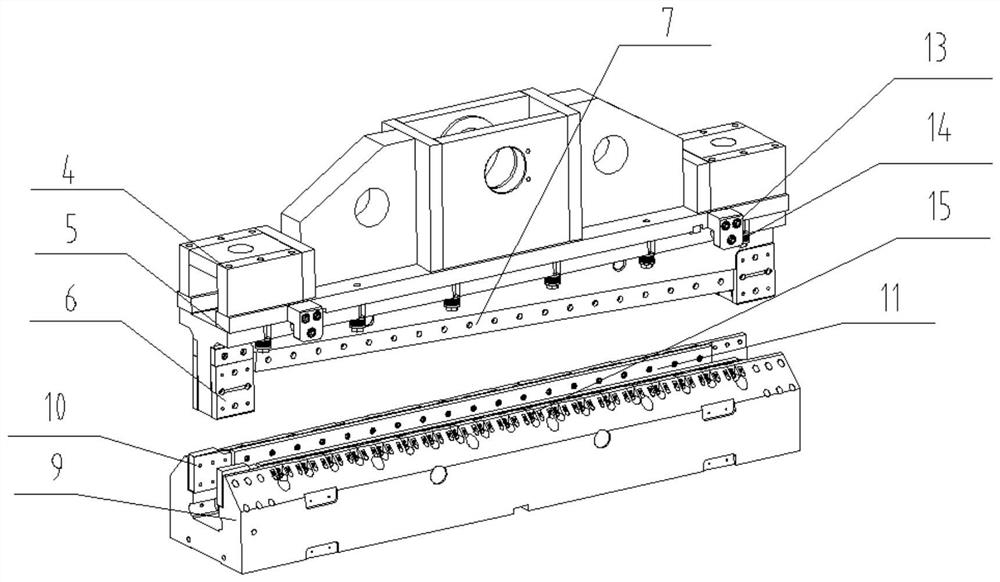
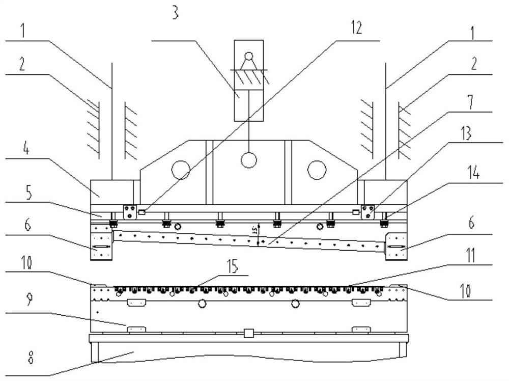
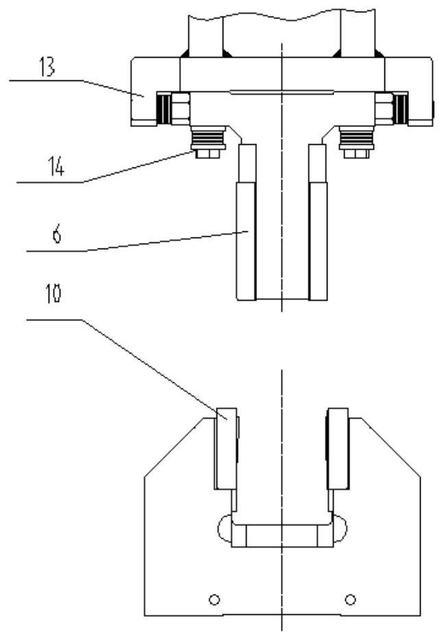
[0044] In this embodiment, the upper knife rest 5 is changed from a fixed type to a floating type, and its specific structure is that the left and right adjustment mechanisms 13 of the upper knife rest are respectively arranged on both sides of the upper knife rest 5 and the upper knife seat 4 along the width direction, It includes stoppers 16 fixed on both sides of the upper knife rest 4, the lower ends of the stoppers 16 extend to both sides of the upper knife rest 5, and a transverse step screw 17 is designed under the stopper 16, and the transverse step screw 17 passes through the stopper. The counterbore of block 16 outsides and disc spring group 18 are locked on the nut 19, and disc spring group 18 is installed in the counterbore of block 16 inboards, and nut 19 contacts the side of upper knife rest 5. The vertical limit mechanism 14 of the upper knife rest includes a vertical adjustment screw, which passes through the opening slot of the upper knife rest 5 and is locked ...

Embodiment 2

[0048] Embodiment 2 is a further optimization scheme based on Embodiment 1. A cutting edge gap adjustment mechanism is designed between the lower blade 11 and the lower tool holder 9, and an adjustment mechanism is arranged at each blade fixing screw. Such as Figure 5-10 As shown, with this mechanism, the cutting edge clearance at each locking screw can be freely adjusted. Equally, also be 2 ° of angles between two lower blades 11, promptly be " eight " shape, this design is to avoid the cutting edge of upper blade 7 from scratching the outside of lower blade 11, helps the blanking of cutting waste material simultaneously. Its cutting edge gap adjustment mechanism includes a plurality of sets of adjusting inclined blocks 22 arranged on the inner side of the lower blade 11 along the length direction of the lower blade 11, and the side of the adjusting inclined blocks 22 close to the lower blade 11 is a slope, The other side opposite to it is a vertical surface, and the adjust...

Embodiment 3

[0053] Embodiment 3 is a further optimization scheme based on Embodiment 2. The original right angle of the belt relief groove 28 is improved to a rounded corner, so that when the lower knife rest 9 is subjected to shear force, the lateral deformation is smaller, and the belt groove is stressed. More reasonable, make lower knife rest 9 not easily deformed.


PUM


Abstract

The invention discloses a double-blade shear device of a steel rolling line strip steel abutted seam laser welding machine. The double-blade shear device is characterized in that an upper tool post isfixedly connected to an upper tool apron; a pair of upper blades is arranged at the lower end of the upper tool post; a lower tool post is fixedly connected to a lower tool apron; a pair of lower blades is arranged at the upper end of the lower tool post; the upper tool post is attached to the upper tool apron through an upper tool post vertical limiting mechanism; upper tool post left and rightadjusting mechanisms are arranged on the two sides of the upper tool post; and a lower shear blade gap adjusting mechanism is designed between the lower blades and the lower tool post. According to the double-blade shear device, the vertical limiting mechanism facilitates automatic alignment of the lower tool post by the upper tool post before shearing, so that lateral impact force on the lower tool post is reduced; the upper tool post left and right adjusting mechanisms limit the displacement distance of the upper tool post, so that the upper tool post does not exceed the automatic guide range to cause direct collision of guide plates; the shear blade gap adjusting mechanism gets rid of a conventional gasket mode to adjust a gap, and adjusts the shear blade gap independently at all points, so that the precision of the shear blade gap in the length direction is higher and more uniform; and the adjusting mechanism is convenient, rapid and practical in adjustment.

Description

technical field [0001] The invention relates to the technical field of double-edged shears, in particular to a double-edged shears device for a steel rolling line strip seam laser welding machine. Background technique [0002] With the rapid development of my country's automobile, bridge, construction, home appliance and other industries that have a large demand for steel, steel companies have higher and higher requirements for the output and quality of high-standard, cost-effective steel. At present, during the use of heavy-duty laser welding machines in the production lines of iron and steel enterprises, the quality of the double-edged shears and the quality of the strips are very strict. The stability of the double-edged shears and the upper and lower The cutting edge clearance of the blade directly affects the quality of cutting and stitching. [0003] The main function of the double-edged shear device is to cut the tail of one roll of strip steel and the head of the ne...

Claims


Application Information

Patent Timeline
Patent Type & Authority Applications(China)
IPC IPC(8): B23D15/04B23D15/14B23D35/00
CPCB23D15/04B23D15/14B23D35/005
Inventor 芦洪波夏思明余磊王卫强刘军陈俊徐剑
Owner 武汉凯奇冶金焊接设备制造有限责任公司
Why Eureka
Try Eureka