
Transformer

A technology of a voltage transformation device and a voltage transformation module, which is applied in the field of transformers and can solve problems such as large separation distances and waste of circuit board area

Active Publication Date: 2016-08-17
DELTA ELECTRONICS INC
View PDF4 Cites 0 Cited by
  • Summary
  • Abstract
  • Description
  • Claims
  • Application Information

AI Technical Summary

Problems solved by technology

In order to solve the problem that the traditional transformer device requires a large separation distance to pass the high voltage insulation test, resulting in a waste of circuit board area

Method used


Image

  • Transformer
  • Transformer
  • Transformer

Examples


Embodiment Construction

[0027] Devices and methods of use of various embodiments of the present invention are discussed in detail below. It should be noted, however, that the present invention provides many possible inventive concepts that can be implemented in various specific scopes. These specific embodiments are only used to illustrate the device and method of use of the present invention, but are not used to limit the scope of claims of the present invention.

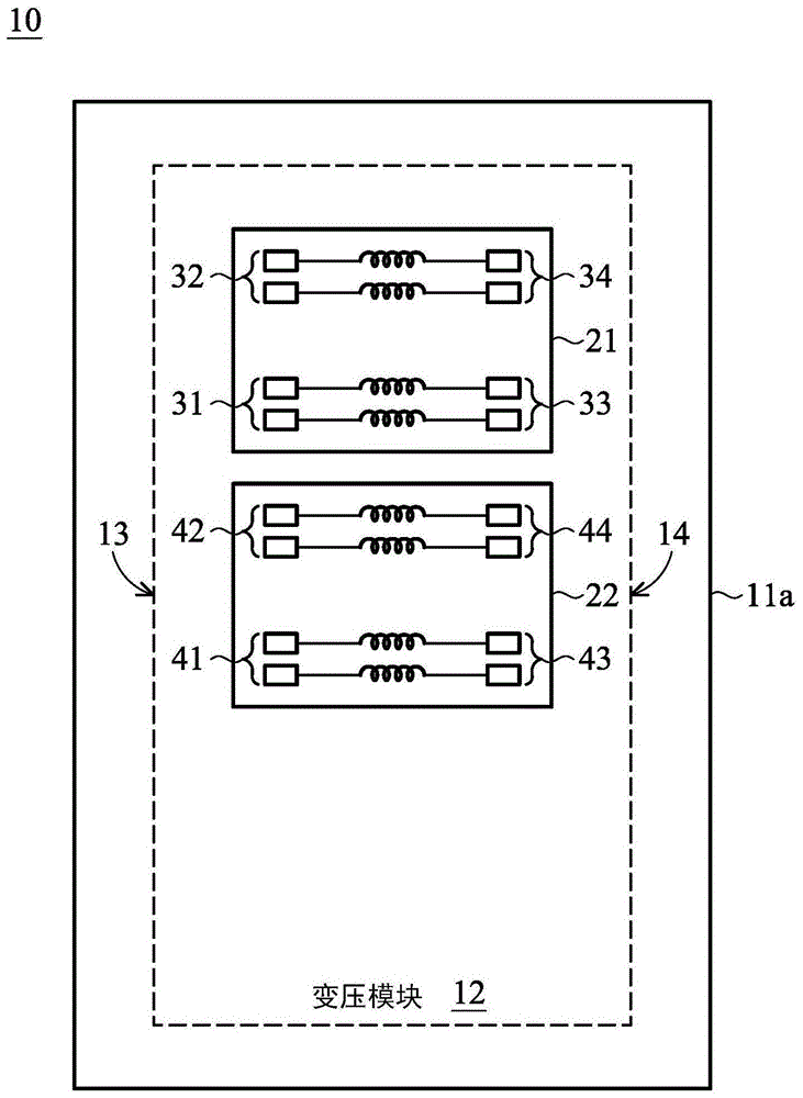
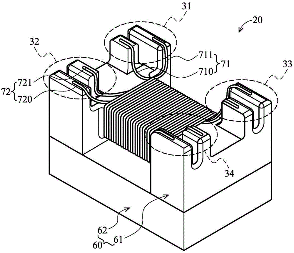
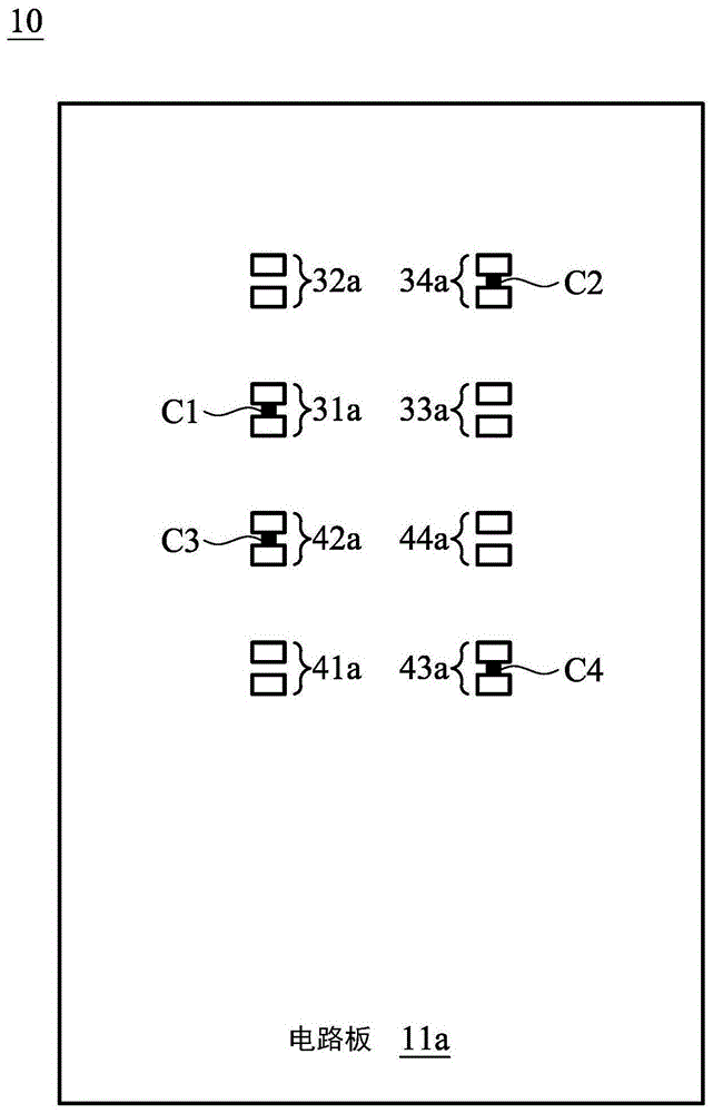
[0028] figure 1 It is a schematic diagram of an embodiment of the transformer device in the present invention. like figure 1 As shown, the transformer device 10 has a circuit board 11 a and a transformer module 12 . The transformer module 12 is disposed on the circuit board 11 a and includes a first transformer unit 21 and a second transformer unit 22 . The first transforming unit 21 and the second transforming unit 22 are disposed on the circuit board 11a and arranged adjacent to each other. like figure 1 As shown, the pin groups 3...


PUM


Abstract

The invention discloses a voltage transformation device, which comprises a circuit board, a voltage transformation module, and first to fourth wires. The transforming module includes a first transforming unit, arranged on the circuit board, having a plurality of first pins and a plurality of second pins; and a second transforming unit, arranged on the circuit board and connected with the first transforming unit Adjacent, there are a plurality of third stitches and a plurality of fourth stitches. The first wire is used to electrically connect the first pin; the second wire is used to electrically connect the second pin; the third wire is used to electrically connect the third pin; and the fourth wire is used to electrically connect the first pin. Four pins. The first pin and the third pin are located on a first side of the transformer module, the second pin and the fourth pin are located on a second side of the transformer module opposite to the first side, and the first pin and the third pin are in phase adjacent.

Description

technical field [0001] The present invention relates to a transformer, in particular to a transformer with freely determined center tap. Background technique [0002] Since the middle tap line of a conventional transformer is fixed, the primary terminal and the secondary terminal are also fixed. When multiple transformers are placed side by side on the circuit board, two adjacent transformers are usually adjacent to different sides (for example, the primary side of the first transformer is adjacent to the secondary side of the second transformer), in order to avoid A high-voltage discharge path is generated between the primary side and the secondary side of the transformer, which usually increases the distance between the transformers. However, increasing the separation distance between different transformers also means that more printed circuit board (PCB) space is required, which requires more board cost, so a method that can save transformer layout area is needed. Cont...

Claims


Application Information

Patent Timeline
Patent Type & Authority Patents(China)
IPC IPC(8): H01F29/02H01F27/29H01F27/30
Inventor 赖秦新陈志泽
Owner DELTA ELECTRONICS INC
Learn More