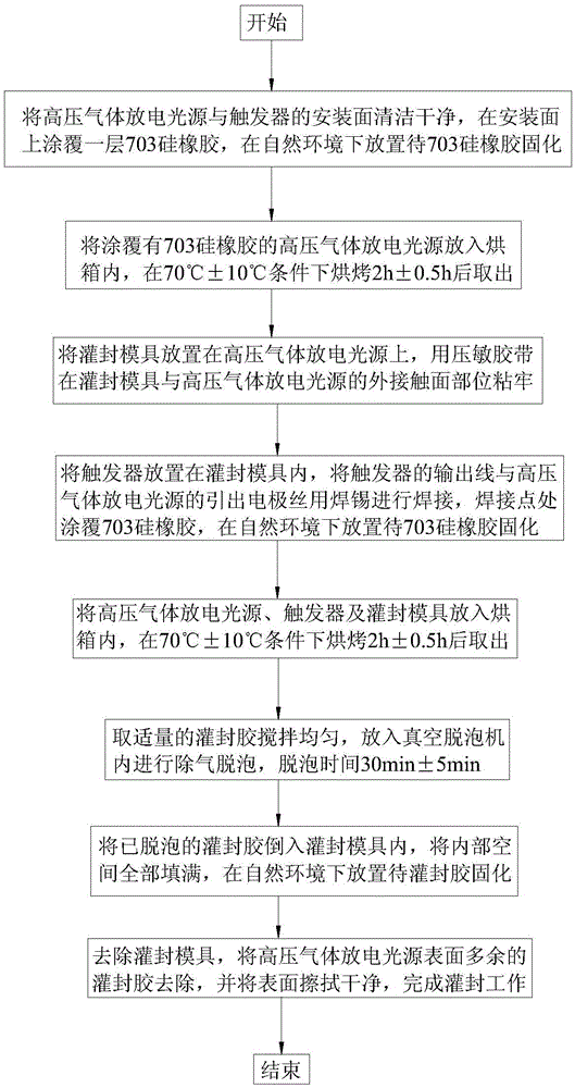
A high-voltage gas discharge light source trigger potting process
A high-pressure gas, trigger technology, applied in the manufacture of ships or lead-in wires, etc., to prevent stress, increase high-voltage insulation performance, and solve the problems of installation firmness and thermal characteristics.
- Summary
- Abstract
- Description
- Claims
- Application Information
AI Technical Summary
Problems solved by technology
Method used
Image
Examples
Embodiment 1
[0033] (1) Clean the installation surface of the high-pressure gas discharge light source and the trigger with absolute ethanol, and coat a layer of 703 silicone rubber on the installation surface. The thickness of the silicone rubber layer is 1mm. silicone rubber curing;
[0034] (2) Put the high-pressure gas discharge light source coated with 703 silicone rubber into the oven, bake it at 70°C for 2 hours, and then take it out;
[0035] (3) The potting mold is placed on the high-pressure gas discharge light source, and the outer contact surface between the potting mold and the high-pressure gas discharge light source is adhered firmly with a pressure-sensitive adhesive tape;
[0036] (4) Place the trigger in the potting mold, weld the output wire of the trigger and the lead-out electrode wire of the high-pressure gas discharge light source with solder, coat the welding point with 703 silicone rubber, place it in the natural environment for 4 hours, and wait for 703 silicone ...
Embodiment 2
[0042] (1) Clean the installation surface of the high-pressure gas discharge light source and the trigger with absolute ethanol, and coat a layer of 703 silicone rubber on the installation surface. The thickness of the silicone rubber layer is 1.2mm. 703 silicone rubber curing;
[0043] (2) Put the high-pressure gas discharge light source coated with 703 silicone rubber into the oven, bake it at 60°C for 2.5 hours, and then take it out;
[0044] (3) The potting mold is placed on the high-pressure gas discharge light source, and the outer contact surface between the potting mold and the high-pressure gas discharge light source is adhered firmly with a pressure-sensitive adhesive tape;
[0045] (4) Place the trigger in the potting mold, weld the output wire of the trigger with the lead-out electrode wire of the high-pressure gas discharge light source with solder, coat the welding point with 703 silicone rubber, place it in the natural environment for 5 hours, and wait 703 sili...
Embodiment 3
[0051] (1) Clean the installation surface of the high-pressure gas discharge light source and the trigger, and coat a layer of 703 silicone rubber on the installation surface. The thickness of the silicone rubber is 1.5mm. Place it in the natural environment for 10 hours, and wait for the 703 silicone rubber to cure;
[0052] (2) Put the high-pressure gas discharge light source coated with 703 silicone rubber into the oven, bake it at 80°C for 2.5 hours, and then take it out;
[0053] (3) The potting mold is placed on the high-pressure gas discharge light source, and the outer contact surface between the potting mold and the high-pressure gas discharge light source is adhered firmly with a pressure-sensitive adhesive tape;
[0054] (4) Place the trigger in the potting mold, weld the output wire of the trigger and the lead-out electrode wire of the high-pressure gas discharge light source with solder, coat the welding point with 703 silicone rubber, place it in the natural envir...
PUM
 Abstract
Description
Claims
Application Information
 - R&D
- Intellectual Property
- Life Sciences
- Materials
- Tech Scout
- Unparalleled Data Quality
- Higher Quality Content
- 60% Fewer Hallucinations
Browse by: Latest US Patents, China's latest patents, Technical Efficacy Thesaurus, Application Domain, Technology Topic, Popular Technical Reports.
© 2025 PatSnap. All rights reserved.Legal|Privacy policy|Modern Slavery Act Transparency Statement|Sitemap|About US| Contact US: help@patsnap.com

