Minitype laying device for power cable

A power cable and small technology, which is applied in the field of small power cable laying devices, can solve the problems of large construction machinery being unable to be used normally, and the increase of cable laying workload and cost, so as to avoid building demolition work, improve the standardization operation level, and save operation time. Time-saving effect

Inactive Publication Date: 2014-10-01
STATE GRID SHANDONG ELECTRIC POWER COMPANY WEIFANG POWER SUPPLY +1
View PDF5 Cites 14 Cited by
  • Summary
  • Abstract
  • Description
  • Claims
  • Application Information

AI Technical Summary

Problems solved by technology

[0002] In the construction of power cable laying, often due to the limitation of laying path size and space structure factors, great mechanical stress is encountered in the traction and transportation of power cables. Usually, large tractors and conveyors are used to overcome these stresses. However, in many construction sites, due to space constraints, large construction machinery cannot be used normally, so that the staff can only temporarily remove the infrastructure that affects the laying of power cables, and even use purely manual cable laying. Many people pull the cable, which increases the workload and cost of cable laying dramatically

Method used


Image

  • Minitype laying device for power cable
  • Minitype laying device for power cable
  • Minitype laying device for power cable

Examples


Embodiment Construction

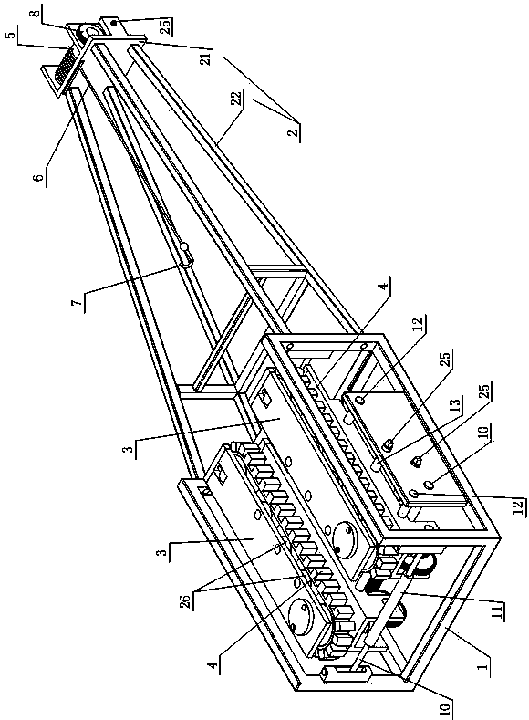
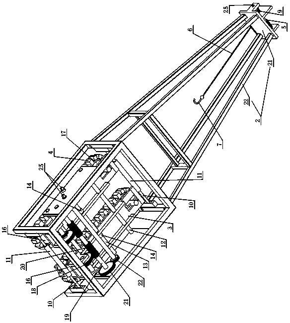
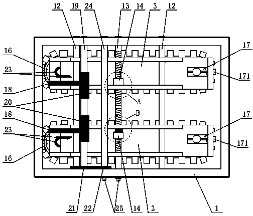
[0023] With reference to the accompanying drawings, one embodiment of the small power cable laying device of the present invention includes a delivery trough 1 and a traction frame 2 detachably connected to the front end of the delivery trough 1, and both ends of the delivery trough 1 in the length direction are open. And a passage for the cables to pass is formed in the conveying trough 1, and the front end of the traction frame 2 is equipped with a traction mechanism that can be connected with the end of the cables.

[0024] Referring to the accompanying drawings, the draw frame 2 includes a draw plate 21 vertically arranged at the front end and a plurality of legs 22 connected to the rear of the draw plate 21. The front ends of the legs 22 are affixed to the draw plate 21, and the rear ends of the legs 22 pass through Bolts or pins are connected with the conveying trough 1. Utilizing the structure of the traction plate 21 and a plurality of legs 22, the traction mechanism c...


PUM


Abstract

The invention relates to a minitype laying device for a power cable. The minitype laying device comprises a conveying chute and a traction frame detachably connected to the front end of the conveying chute. The two ends in the length direction of the conveying chute are open, a channel allowing the cable to penetrate through is formed in the conveying chute, and a traction mechanism capable of being connected with the end of the cable is installed at the front end of the traction frame; two conveying racks capable of sliding in the width direction of the conveying chute are installed in the conveying chute in a spaced mode, a spacing adjustment mechanism used for adjusting the distance between the two conveying racks is connected between the two conveying racks, each conveying rack is surrounded by a rubber chain, the two rubber chains are matched with each other so that the cable can be clamped between the two conveying racks, the conveying directions of the two rubber chains are identical and the two rubber chains are synchronously driven by a power conveying mechanism installed in the conveying chute. According to the minitype laying device for the power cable, traction and conveying operation of the cable can be completed in narrow space, the integrated structure is stable and reliable, operation is convenient and fast to achieve, the workload of cable laying can be lowered, and human input is reduced.

Description

technical field [0001] The invention relates to a small-sized power cable laying device. Background technique [0002] In the construction of power cable laying, often due to the limitation of laying path size and space structure factors, great mechanical stress is encountered in the traction and transportation of power cables. Usually, large tractors and conveyors are used to overcome these stresses. However, in many construction sites, due to space constraints, large construction machinery cannot be used normally, so that the staff can only temporarily remove the infrastructure that affects the laying of power cables, and even use purely manual cable laying. Many people carry out cable pulling, which makes the workload and cost of cable laying increase sharply. Especially under the background of widespread popularization and application of compact large-capacity high-pressure inflatable tanks, the above-mentioned problems appear more prominently. Contents of the inventi...

Claims


Application Information

Patent Timeline
Patent Type & Authority Applications(China)
IPC IPC(8): H02G1/06
Inventor 崔文生张宏滨张明岗阎波董道玉黄学增孟博陈伟涛
Owner STATE GRID SHANDONG ELECTRIC POWER COMPANY WEIFANG POWER SUPPLY
Why Eureka
Try Eureka