Bottle transport device

A transmission device and bottle technology, which is applied in the directions of transportation and packaging, conveyor objects, etc., can solve the problems of bottle 3 deformation, inaccurate measurement, bottle mouth pollution, etc., and achieve the effects of low cost, reduced frictional resistance, and simple structure.

Inactive Publication Date: 2013-06-26
JIANGSU NEWAMSTAR PACKAGING MACHINERY
View PDF10 Cites 6 Cited by
  • Summary
  • Abstract
  • Description
  • Claims
  • Application Information

AI Technical Summary

Problems solved by technology

The disadvantage is: when the bottle 3 is being transported, there is sliding friction between the bottom of the bottle 3 and the bottle supporting plate 4, and the inside of the bottle 3 has been filled with liquid, so that the friction force is relatively large. If the bottle wall of the bottle 3 is thin, The star wheel 1 will squeeze the bottle 3, causing the bottle 3 to deform, and the unpackaged liquid will be squeezed out from the bottle mouth, which will not only cause inaccurate measurement, but also cause pollution of the bottle mouth

Method used


Image

  • Bottle transport device
  • Bottle transport device
  • Bottle transport device

Examples


Embodiment Construction

[0016] The bottle conveying device of the present invention will be further described in detail through specific examples below.

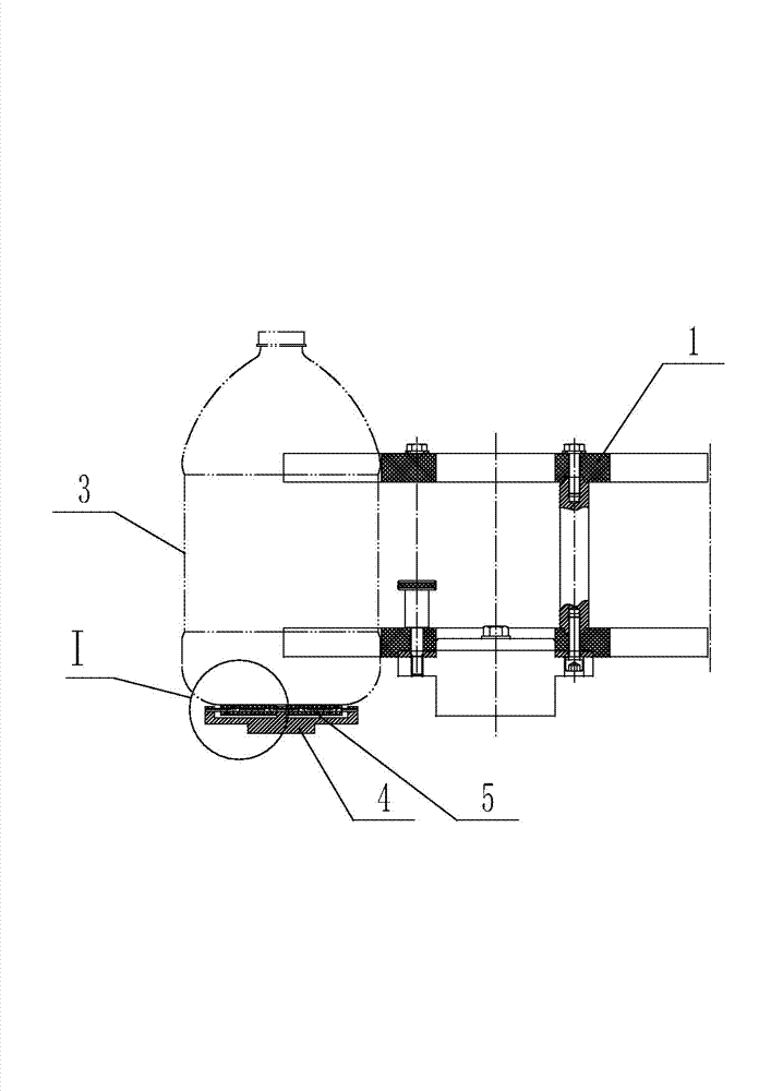
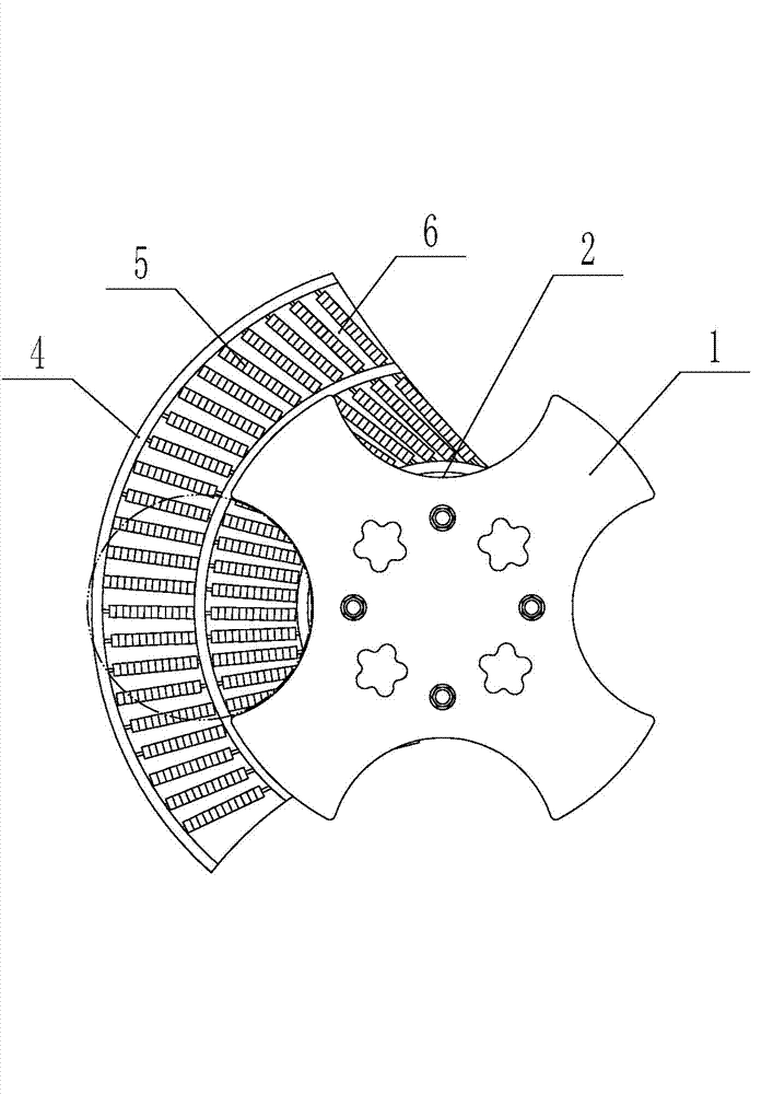
[0017] Such as figure 1 , figure 2 As shown, the bottle conveying device includes a rotatable star wheel 1. Several bottle slots 2 are arranged on the peripheral wall of the star wheel 1. The size of the bottle slots 2 matches the size of the bottle 3. The bottom of the star wheel 1 is provided with Bottle supporting plate 4, in the present embodiment, bottle supporting plate 4 is fan-shaped structure, and the structure of bottle supporting plate can be changed according to the actual situation on the spot, and described bottle supporting plate 4 is provided with several freely rotatable rolling bodies. The rotating direction of the rolling body is consistent with the conveying direction of the bottle 3 .

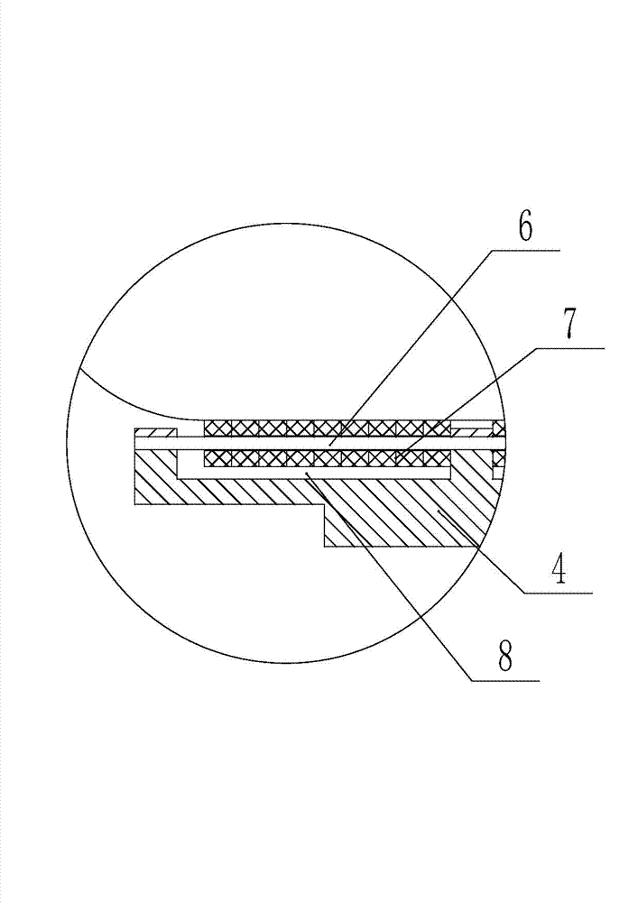
[0018] As a preferred solution, the rolling elements are rollers 5 . Such as figure 1 , image 3 As shown, the roller 5 includes a roll...


PUM


Abstract

The invention relates to a bottle transport device which comprises a star wheel which can rotate, wherein a plurality of bottle grooves are formed in the periphery wall of the star wheel, and the sizes of the bottle grooves are matched with the size of the bottle. A bottle supporting plate is arranged below the star wheel, and a plurality of rolling bodies which can freely rotate are arranged in the bottle supporting plate. The bottle transport device is suitable for a filling production line, is slightly improved based on a traditional bottle transport device, enables a bottle bottom and the bottle supporting plate to conduct rolling friction when the bottle is transported, and greatly reduces friction resistance. The star wheel does not produce squeezing on the bottle, so that deformation of the bottle does not occur, liquid is not squeezed out of a bottle opening, the phenomenon of inaccurate metering is avoided, and pollution on the bottle opening does not occur.

Description

technical field [0001] The invention relates to the technical field of filling equipment, in particular to a transmission device for filled thin-walled bottles. Background technique [0002] In the filling production line, after the bottles are filled in the rotary filling machine, the filled bottles are transferred to the capping machine through the bottle conveying device. Such as Figure 4 As shown, the traditional bottle conveying device includes a rotatable star wheel 1, several bottle grooves 2 are arranged on the peripheral wall of the star wheel 1, the size of the bottle groove 2 matches the size of the bottle 3, and the bottom of the star wheel 1 is arranged Bottle holder plate 4 is arranged. When in use, the filled bottle 3 is placed on the bottle support plate 4, and a part of the bottle 3 is set in the bottle groove 2 of the star wheel 1. With the rotation of the star wheel 1, the bottle 3 is placed on the bottle support plate 4 Relatively slide to realize the ...

Claims


Application Information

Patent Timeline
Patent Type & Authority Applications(China)
IPC IPC(8): B65G47/74B65G47/84
Inventor 孙建春高擎宇何德平
Owner JIANGSU NEWAMSTAR PACKAGING MACHINERY
Why Eureka
Try Eureka