
Stroboscopic-free LED lighting circuit and device

A technology of LED lighting without stroboscopic, applied in lighting devices, electric lamp circuit layout, electric light source and other directions, can solve the problems of low output power, inconstant output power, large number of LED lights, etc., to achieve simple implementation and small changes Effect

Active Publication Date: 2014-10-01
SHENZHEN SUNMOON MICROELECTRONICS
View PDF7 Cites 3 Cited by
  • Summary
  • Abstract
  • Description
  • Claims
  • Application Information

AI Technical Summary

Problems solved by technology

This control method can ensure a high power factor, but because the number of LED lights is different in different opening stages, the output power changes. When the front stage is turned on, the number of LED lights is small and the current is small, the output power is small, and the lights are dim; The number of LED lights is large and the current is large, the output power is large, and the lights are bright
Therefore, affected by the curve output relationship of the power supply voltage and the sudden change of the current, the output power is not constant, resulting in an unstable luminous flux output, and serious stroboscopic phenomenon, which is not conducive to the long-term use of LED lights

Method used


Image

  • Stroboscopic-free LED lighting circuit and device
  • Stroboscopic-free LED lighting circuit and device
  • Stroboscopic-free LED lighting circuit and device

Examples


Embodiment Construction

[0022] Embodiments of the present invention are described in detail below, examples of which are shown in the drawings, wherein the same or similar reference numerals designate the same or similar elements or elements having the same or similar functions throughout. The embodiments described below by referring to the figures are exemplary only for explaining the present invention and should not be construed as limiting the present invention.

[0023] The above solution proposed by the present invention, by adjusting the opening or closing of the LED lamp group, and adjusting the size of the output current of the LED lamp group, can realize the equal output power of the LED lamp group that is turned on in each time period, thereby solving the problem of The serious defect of stroboscopic phenomenon in the prior art realizes step-by-step turning on of LED lights in different stages, all of which have the same output power, meeting the actual demand of no stroboscopic phenomenon. ...


PUM


Abstract

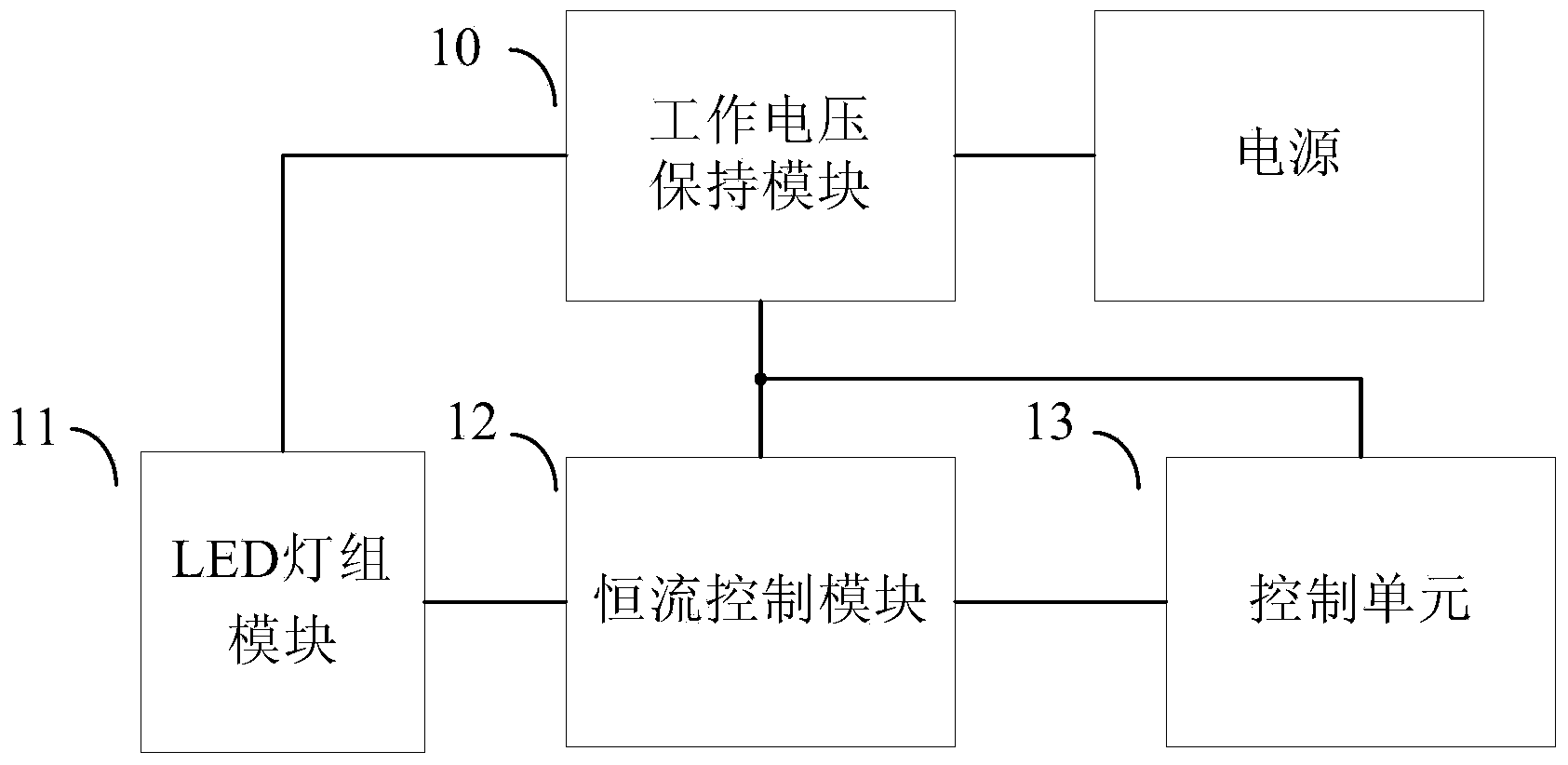
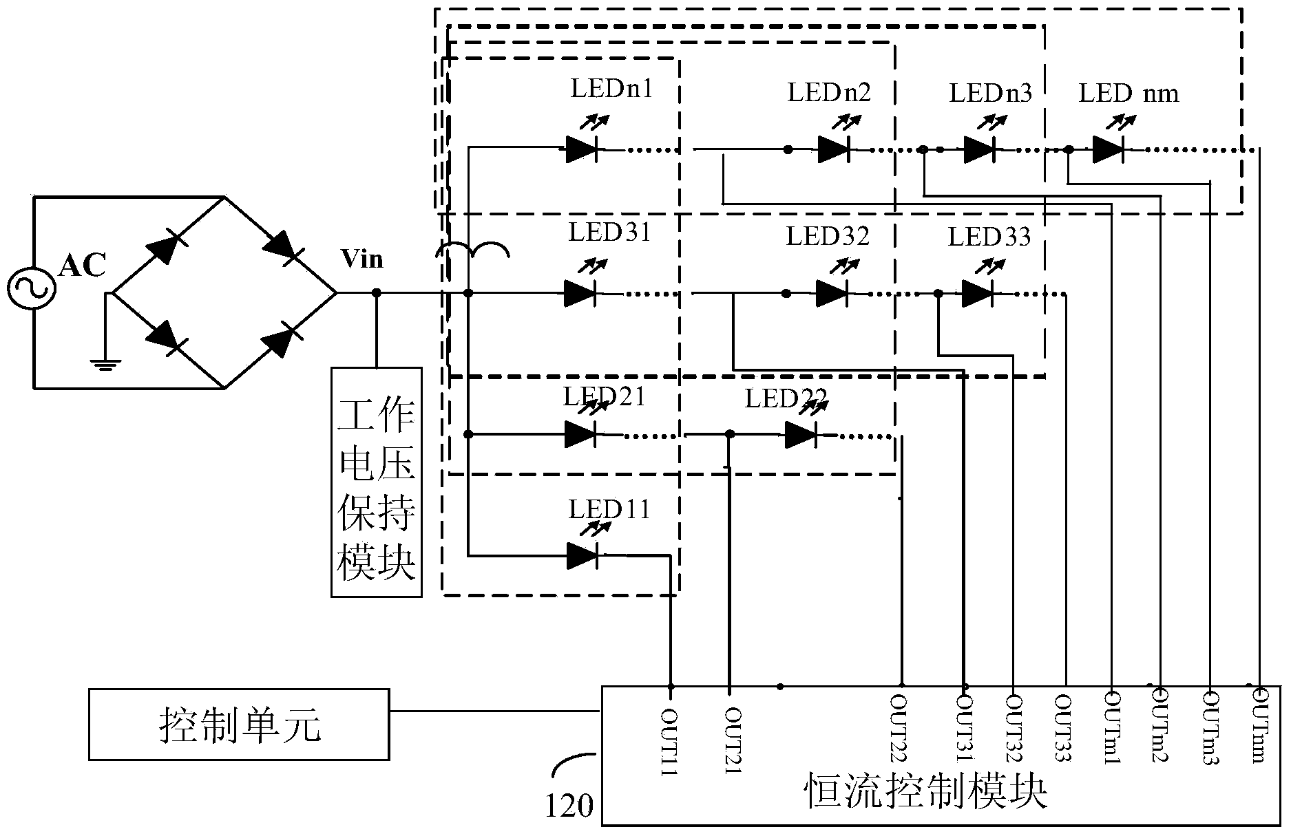
The embodiment of the invention provides a stroboscopic-free LED lighting circuit which comprises an LED lamp set module, a work voltage keeping module, a constant-current control module and a control unit. The LED lamp set module is divided into a plurality of dynamic matrixes, the constant-current control module is controlled by the control unit to turn on or turn off corresponding LED lamp sets and control current of the corresponding LED lamp sets to be constant, and the control unit can control the constant-current control module to achieve switching between the dynamic matrixes according to voltage change of an input line network. The embodiment of the invention further provides a device with the lighting circuit. According to the stroboscopic-free LED lighting circuit and the device, the constant-current control module is controlled by the control unit to achieve the purpose of turning on or turning off the different LED lamp sets according to the voltage change of the input line network. Furthermore, the output power of LED lamps can be kept constant in different time periods by controlling the output current of the turned-on LED lamp sets, the luminous flux output can be kept constant, and the stroboscopic-free requirement can be met.

Description

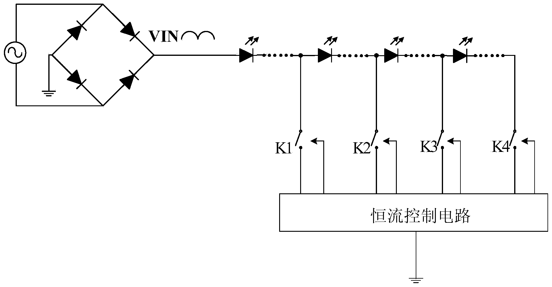
technical field [0001] The invention relates to the field of LED driving, in particular, the invention relates to a flicker-free LED lighting circuit and a device. Background technique [0002] At present, the linear constant current scheme is widely used in small and medium power LED constant current systems due to its simple system structure. The traditional high power factor LED linear constant current control circuit often adopts the method of turning on LED lights step by step in order to achieve high power factor. [0003] Such as figure 1 As shown, when the input voltage rises, the LED lights of different stages are turned on step by step, and the output current gradually increases; when the input voltage drops, the LED lights of different stages are turned off step by step in the opposite direction, and the output current gradually decreases. This control method can ensure a high power factor, but because the number of LED lights is different in different opening s...

Claims


Application Information

Patent Timeline
Patent Type & Authority Applications(China)
IPC IPC(8): H05B37/02
Inventor 林道明李照华王乐康胡乔赵春波谢靖
Owner SHENZHEN SUNMOON MICROELECTRONICS
Learn More