Connector with wire cover

A technology for connectors and wires, applied in the field of connectors with wire covers, can solve problems such as poor assembly characteristics and inability to easily assemble wire covers, and achieve the effect of improving versatility

Active Publication Date: 2014-10-01
YAZAKI CORP
View PDF7 Cites 12 Cited by
  • Summary
  • Abstract
  • Description
  • Claims
  • Application Information

AI Technical Summary

Problems solved by technology

[0009] In the conventional connector with the wire cover described above, since the mating parts are combined by closing the half-cut tubular parts (connection adapter and di

Method used


Image

  • Connector with wire cover
  • Connector with wire cover
  • Connector with wire cover

Examples


Embodiment Construction

[0041] Embodiments of the present invention will be described below with reference to the drawings.

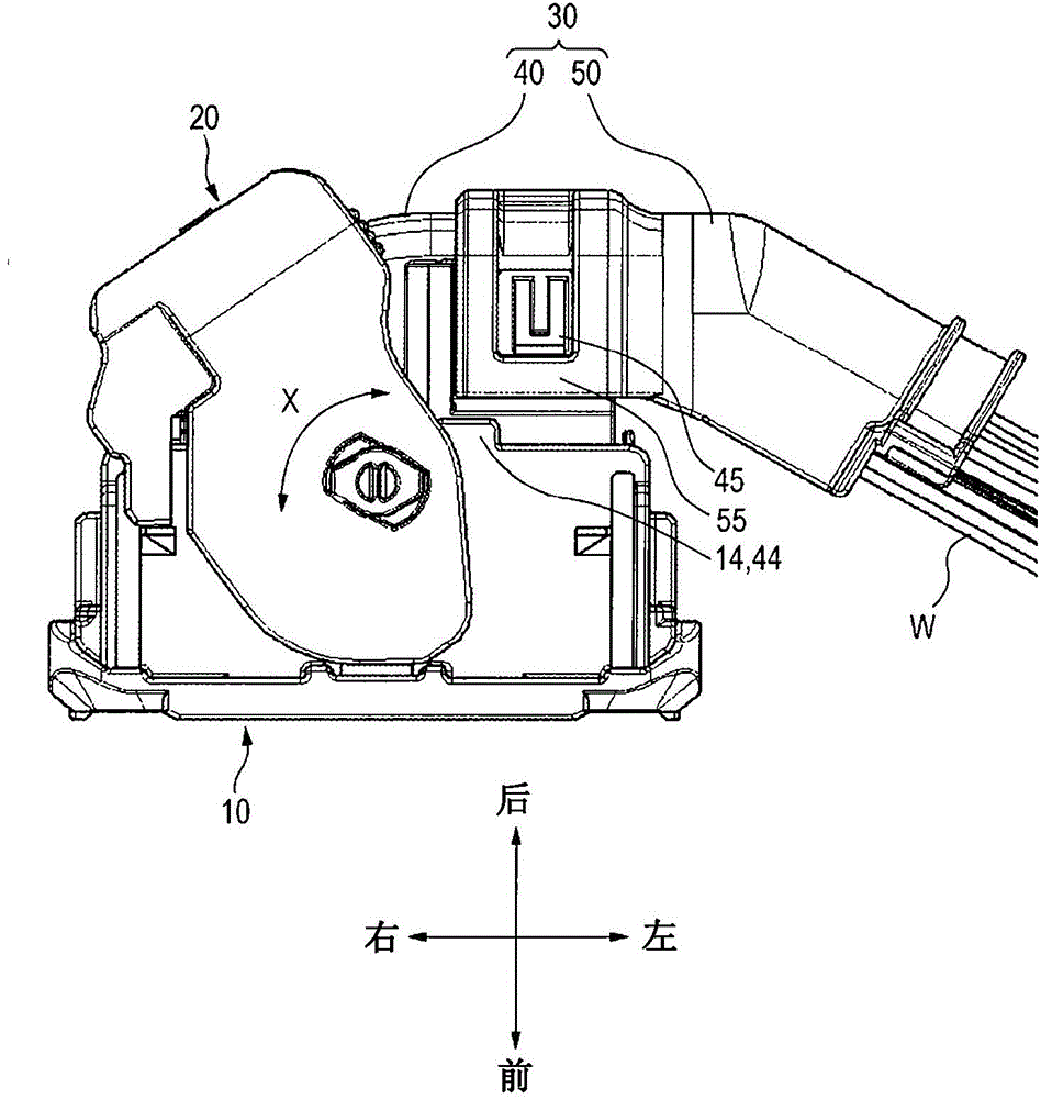
[0042] In the following description, it is assumed that the side where the connector with a wire cover of this embodiment is fitted to the mating connector is the front side, the side opposite to the front side is assumed to be the rear side, and a large number of terminals ( (not shown in the drawings) are aligned in the right-left direction or the left-right direction.

[0043] Such as figure 1As shown, the connector with a wire cover of this embodiment includes: a connector body 10 , a wire cover 30 and a lever 20 . The wires W are led out from the rear of the connector body 10 rearward. The wire cover 30 is attached to the rear portion of the connector body 10, and after the wire is bent once toward one side (the left side opposite to the side to which the lever 20 to be described below is attached), it will be released from the connector body. The wire W drawn out from...


PUM


Abstract

A connector includes a connector body and a wire cover divided into first and second covers. A bend guiding wall is provided in the first cover and laterally bends the wires drawn out backwards from a rear of the connector body. A sliding-type first locking mechanism is provided between one end of the first cover and the rear of the connector body and slides the first cover and locks the first cover and the connector body. A extraction guiding wall is provided in the second cover and guides and extracts the wires, which are laterally bent by the bend guiding wall. A sliding-type second locking mechanism is provided between one end of the second cover and the other end of the first cover and slides the second cover and locks the second cover and the first cover.

Description

technical field [0001] The present invention relates to a connector with an electric wire cover, in which an electric wire cover guiding the lead-out direction of electric wires is attached to the rear of the connector body. Background technique [0002] In Patent Document 1, an example of a connector with a wire cover in which a wire cover including a half-cut tubular connection adapter and a half-cut tubular direction regulating protector is attached to the connector body is disclosed. of the rear. In this connector with a wire cover, the wire drawn out from the rear of the connector body is guided toward a predetermined direction via the adapter with a direction restricting protector attached to the rear of the connector body. [0003] In the connector with the wire cover, each connection end of the connection adapter and the direction restricting protector is provided with a half-cut tubular fitting pipe fitted with a fitting portion. By closing the connection adapter ...

Claims


Application Information

Patent Timeline
IPC IPC(8): H01R13/506H01R13/58
CPCH01R13/5841H01R13/62938H01R13/506
Inventor 滨井强向岛伸幸
Owner YAZAKI CORP
Why Eureka
Try Eureka