Roller and rolling device thereof

A technology of roller and roller surface, which is applied in the direction of grain processing, etc., can solve the problem of low first-time yield and achieve the effect of improving first-time yield, service life and wear resistance

Active Publication Date: 2014-10-08
胡沿东
View PDF12 Cites 19 Cited by
  • Summary
  • Abstract
  • Description
  • Claims
  • Application Information

AI Technical Summary

Problems solved by technology

However, when the stud roller squeezes or crushes materials, the first-time yield is not high, which is 10% to 16%. In addition, the service life of the stud roller is 12000 to 15000 hours, and the wear amount of 2100 hours is 3.2mm

Method used


Image

  • Roller and rolling device thereof
  • Roller and rolling device thereof
  • Roller and rolling device thereof

Examples


Embodiment 1

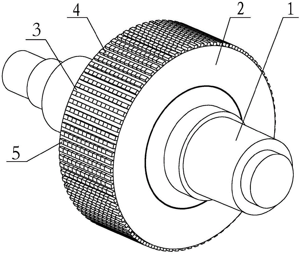
[0025] Such as figure 1 The shown roller includes a roller shaft 1 and a base body 2, on which a rib 4 is arranged, and the rib 4 is continuously formed by closely arranged protrusions 5 along the axial direction of the roller. In addition, the The bump 5 is made of high wear-resistant material. This roller is used in rolling equipment such as roller presses and vertical mills.

[0026] With the roller of this embodiment, the first-time yield is increased to 22%, the service life is increased to 15,000 hours, and the wear amount is reduced to 2.5mm after 2,100 hours of use.

Embodiment 2

[0028] Such as figure 1 The shown roller includes a roller shaft 1 and a base body 2, on which a rib 4 is arranged, and the rib 4 is continuously formed by closely arranged protrusions 5 along the axial direction of the roller. In addition, the The bump 5 is made of high wear-resistant hard alloy, and the height L1 of the bump 5 above the roller surface 3 is 7mm.

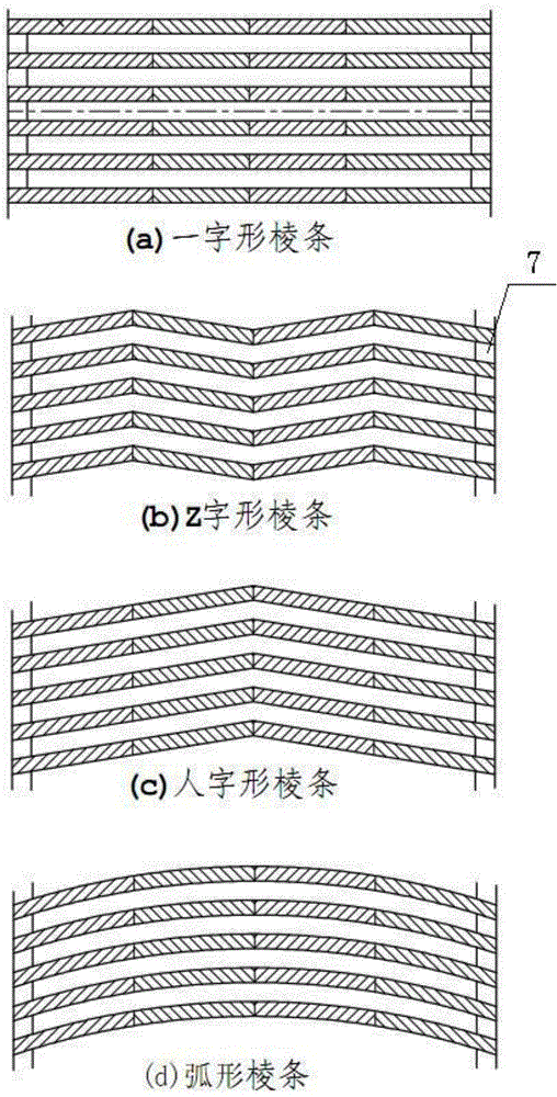
[0029] In addition if image 3 The projections 5 forming the same rib 4 shown have the same height above the roll surface 3 . This roller is used in rolling equipment such as roller presses and vertical mills.

[0030] With the roller of this embodiment, the first-time yield is increased to 25%, the service life is increased to 16,500 hours, and the wear amount is reduced to 2.5mm after 2,100 hours of use.

Embodiment 3

[0032] Such as figure 1 The shown roller includes a roller shaft 1 and a base body 2, on which a rib 4 is arranged, and the rib 4 is continuously formed by closely arranged protrusions 5 along the axial direction of the roller. In addition, the The bump 5 is made of high wear-resistant hard alloy. The bump 5 is connected to the base 2 through a groove 6 provided on the base 2, and the bump 5 is located in the groove 6 by being embedded.

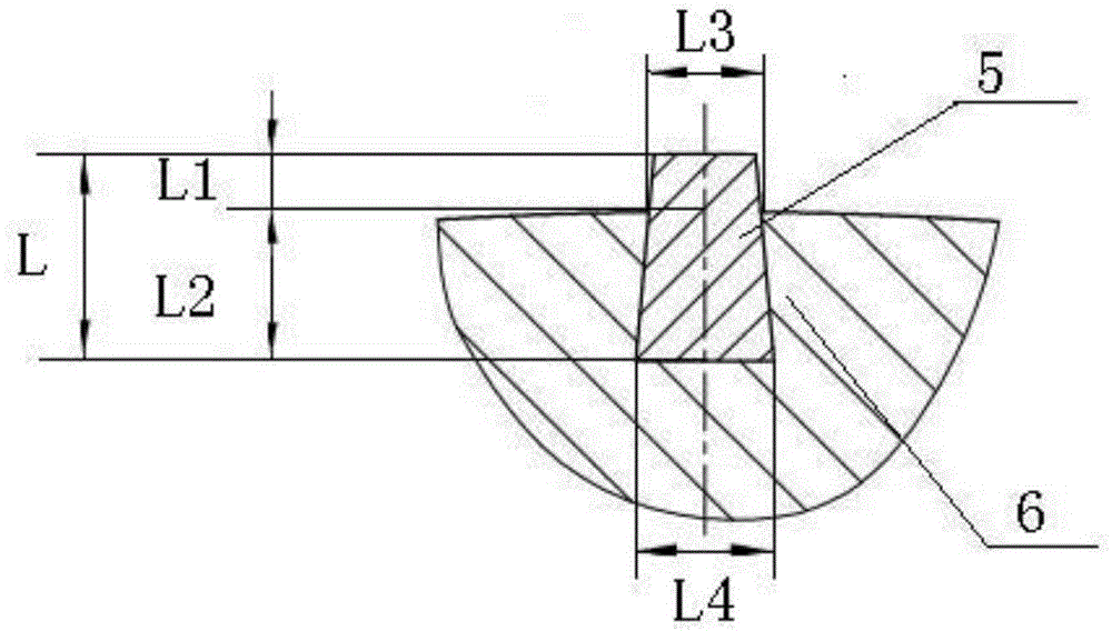
[0033] Such as figure 2 As shown, the width L4 of the bottom surface of the bump 5 is not less than the width L3 of the intersecting surface of the bump and the roller surface 3, the height L1 of the bump 5 above the roller surface 3 is 7 mm, and the overall height L of the bump 5 is 47 mm.

[0034] In addition if image 3 The shown bumps 5 forming the same rib 4 are at the same height above the roll surface 3 , and the bumps 5 are arranged on the roll surface 3 to form a straight rib 4 . This roller is used in rolling equipment such as...


PUM


Abstract

The invention provides a roller. The roller comprises a basal body (2) which is provided with ribs (4). The roller is characterized in that each rib (4) is formed by continuously and densely arranging convex blocks (5) along the axial direction of the roller, and each convex block (5) is made from a high-abrasion-resistance material. According to the invention, not only can the one-step finishing rate of the roller be increased, but also the service life of the roller is prolonged, and the abrasion resistance of the roller is improved. The one-step finishing rate of the roller can reach 22 to 30 percent, the service life of the roller can reach 15000h to 20000h, and the abrasion degree of the roller working for 2100h is only 2.5mm.

Description

technical field [0001] The invention relates to a roller for grinding or comminuting, and also to a rolling device comprising such a roller. Background technique [0002] Rollers are generally used in rolling equipment to grind or crush materials. Usually, when the roller rolls the material, it is realized by using the protrusions arranged on the surface of the roller base. The protrusions in the existing equipment are mainly formed by setting several studs higher than the surface of the base body on the surface of the base body. There is an interval between the studs and the studs. The studs are used to squeeze the material to achieve the effect of grinding or crushing the material. . However, when the stud roller squeezes or crushes materials, the first-time yield is not high, which is 10% to 16%. In addition, the service life of the stud roller is 12000 to 15000 hours, and the wear amount of 2100 hours is 3.2mm. Contents of the invention [0003] The object of the pr...

Claims


Application Information

Patent Timeline
Patent Type & Authority Applications(China)
IPC IPC(8): B02C4/30
CPCB02C4/305B02C4/30B02C2210/02
Inventor 张珂张进才胡沿东
Owner 胡沿东
Why Eureka
Try Eureka