
Cut-off knife cooling mechanism for cutting bed

A cooling mechanism and cutting knife technology, applied in the field of cutting machines, can solve the problems of cooling gas waste, cutting knife, rotating bearing heating, etc., and achieve the effects of reducing cooling costs, high cooling efficiency, and high cooling accuracy

Active Publication Date: 2014-10-08
BULLMER ELECTROMECHANICAL TECH
View PDF4 Cites 8 Cited by
  • Summary
  • Abstract
  • Description
  • Claims
  • Application Information

AI Technical Summary

Problems solved by technology

However, although the above-mentioned air cooling device can cool the cutting knife, in actual use, since the cutting knife is pierced in the cutter head, and the cutter head needs to rotate, the nozzle of the air cooling device must avoid the radius of rotation of the cutter head. , so the nozzle is relatively far away from the cutting knife; in addition, the cooling air flow ejected from the nozzle is not closed, so most of the cooling air blowing on the cutting knife does not act on the cutting knife, so the cooling effect of the above-mentioned air cooling device on the cutting knife is not good. , and also cause waste of cooling gas
If the cutting knife is not effectively cooled, it will easily cause the cutting knife, guide bearing, and rotating bearing to heat up, which will cause heat deformation of the cutting knife, guide bearing, and rotating bearing.

Method used


Image

  • Cut-off knife cooling mechanism for cutting bed
  • Cut-off knife cooling mechanism for cutting bed
  • Cut-off knife cooling mechanism for cutting bed

Examples


Embodiment Construction

[0054] The implementation of the present invention will be illustrated by specific specific examples below, and those skilled in the art can easily understand other advantages and effects of the present invention from the contents disclosed in this specification.

[0055] It should be noted that the structures, proportions, sizes, etc. shown in the drawings attached to this specification are only used to match the content disclosed in the specification, for those who are familiar with this technology to understand and read, and are not used to limit the implementation of the present invention. Limiting conditions, so there is no technical substantive meaning, any modification of structure, change of proportional relationship or adjustment of size, without affecting the effect and purpose of the present invention, should still fall within the scope of the present invention. The disclosed technical content must be within the scope covered. At the same time, terms such as "upper"...


PUM


Abstract

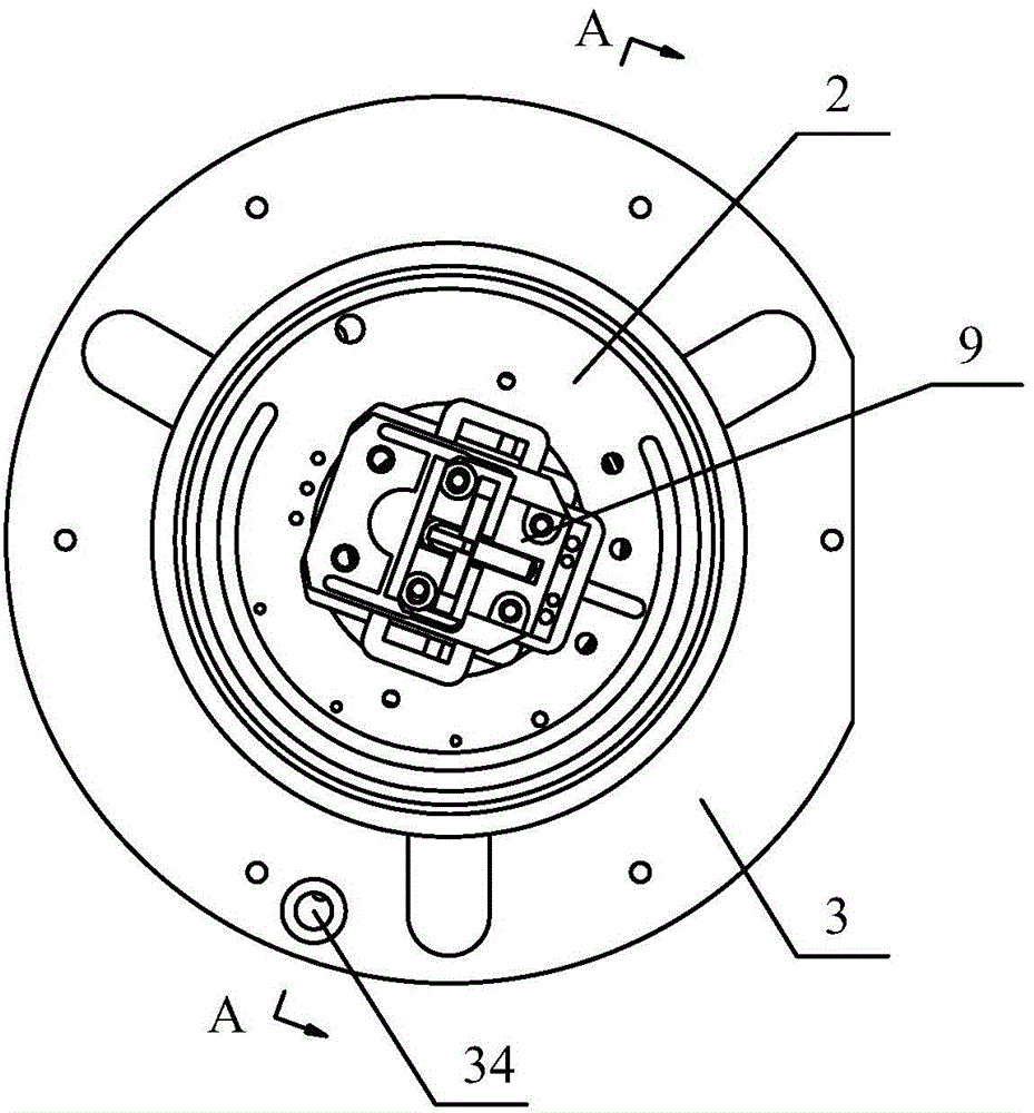
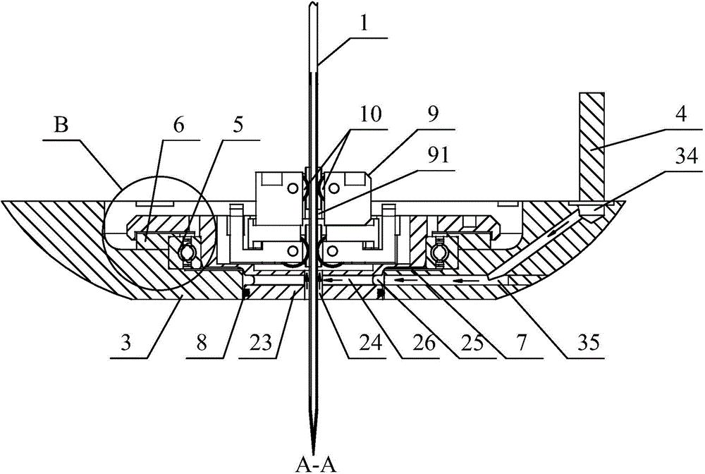
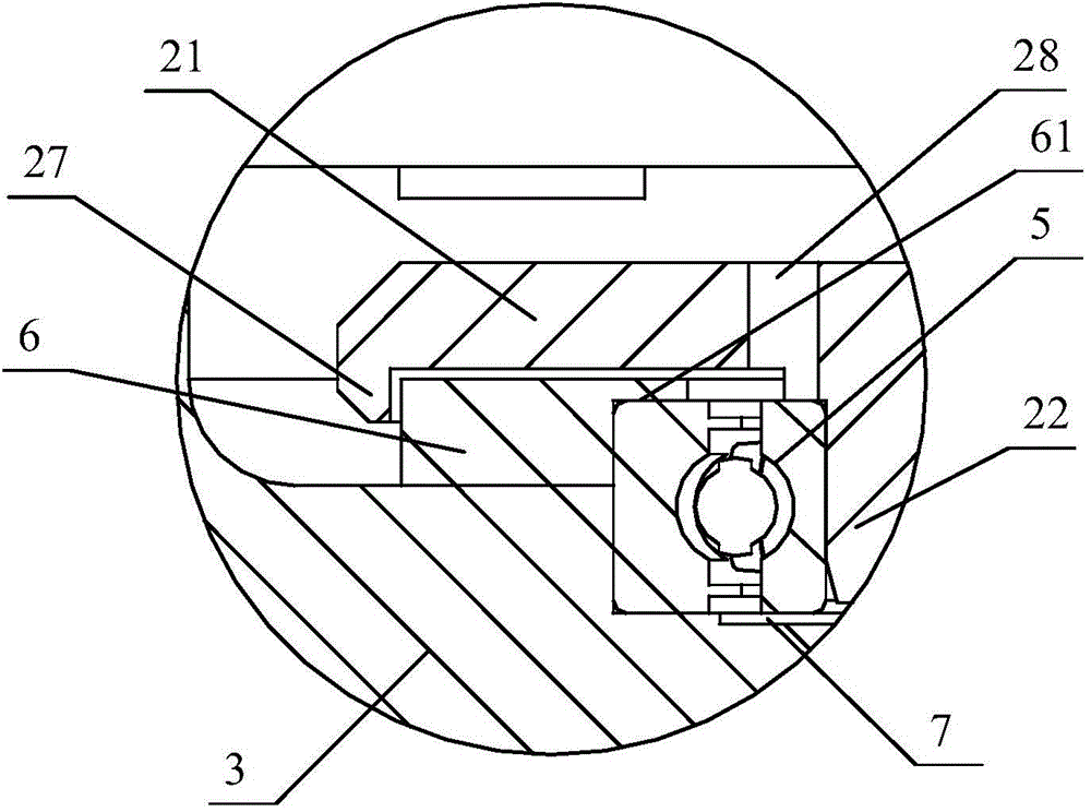
The invention provides a cut-off knife cooling mechanism for a cutting bed. The cut-off knife cooling mechanism comprises a rotating disc, a cut-off knife and a pressing disc. A first containing groove, a second containing groove and a third containing groove are formed in the pressing disc. The rotating disc comprises a protruding edge arranged in the first containing groove, a rotating disc body arranged in the second containing groove and a protruding portion arranged in the third containing groove. A first through hole allowing the cut-off knife to penetrate through is formed in the protruding portion. The upper end face of the pressing disc is provided with an air inlet. The air inlet is connected with an air inlet device used for supplying cooling air. A first air inlet hole is formed in the pressing disc. An annular groove is formed in the peripheral face of the protruding portion. A plurality of second air inlet holes are formed in the protruding portion. The first air inlet hole is communicated with the air inlet and the annular groove. The second air inlet holes are communicated with the annular groove and the first through hole. According to the cut-off knife cooling mechanism for the cutting bed, the cooling air sequentially enters the first air inlet hole, the annular groove, the second air inlet holes and the first through hole through the air inlet in the pressing disc so as to directly blow and cool the cut-off knife penetrating into the first through hole, and the cut-off knife cooling mechanism is high in cooling precision and cooling efficiency.

Description

technical field [0001] The invention relates to a cutting machine, in particular to a cutting blade cooling mechanism for the cutting machine. Background technique [0002] A cutting bed is a sewing device used to automatically cut fabrics and is widely used in the garment manufacturing industry. The cutting bed mainly includes a cutting table, a knife seat, a knife rest, a cutting knife, an operation panel and a vacuum suction device. The cutting knife is installed on the knife seat, and the knife seat is installed on the knife rest. Make the cutter complete various curves or straight cuts. In the process of cutting the fabric, the knife frequency of the knife is relatively fast, and its high-speed movement in the cutting process will easily cause the temperature of the knife to rise, so that the cut fabric will be damaged due to excessive temperature, and it will also accelerate Cutter wear. In order to reduce the temperature of the cutter during the cutting process, a ...

Claims


Application Information

Patent Timeline
Patent Type & Authority Applications(China)
IPC IPC(8): D06H7/00
Inventor 娄正宇周超姚金领杜能平
Owner BULLMER ELECTROMECHANICAL TECH
Learn More