Phase change cooling system
A phase change cooling and condenser technology, applied in electrical components, electrical solid devices, circuits, etc., can solve the problems of low heat dissipation efficiency, corrosion and damage of electrical components, reduced performance and working life of electrical components, etc., to improve the cooling accuracy. , the effect of improving heat transfer efficiency
- Summary
- Abstract
- Description
- Claims
- Application Information
AI Technical Summary
Problems solved by technology
Method used
Image
Examples
Embodiment 1
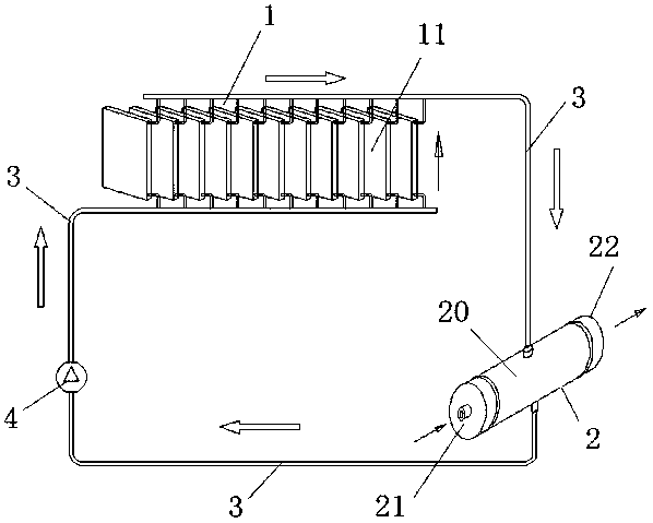
[0023] Such as figure 1 As shown, a phase change cooling system includes an evaporating part 1, a condensing part 2 and an evaporating and condensing pipeline 3; the evaporating and condensing pipeline 3 connects the evaporating part 1 and the condensing part 2 into a continuous circulation loop; the circulation loop is filled with Liquid working medium.
[0024] Specifically, the evaporating part 1 is composed of a plurality of heat absorbing plates 11 arranged in an array and penetrating inside, the tops of the several heat absorbing plates 11 are connected to the inlet of the condensing part 2, and the bottoms of the several heat absorbing plates 11 are connected to the outlet of the condensing part 2 to absorb heat. A circulation pump 4 is provided on the evaporation and condensation pipeline 3 between the bottom of the plate 11 and the outlet of the condensing part 2, and the condensing part 2 is a water condenser, wherein the water condenser includes a cylinder 20 and a ...
Embodiment 2
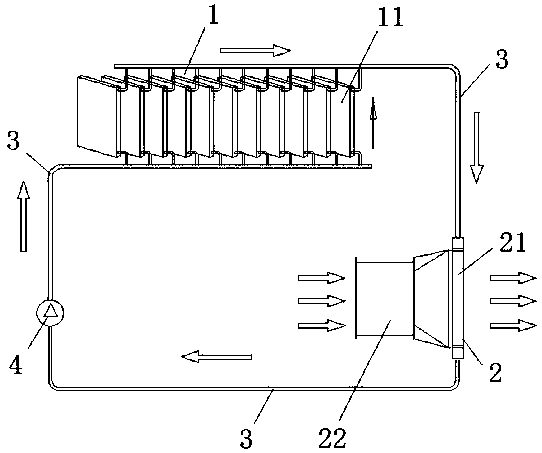
[0029] Such as figure 2 As shown, the phase change cooling system in this embodiment is basically the same as that of the first embodiment, and also includes an evaporation part 1, a condensation part 2, and an evaporation and condensation pipeline 3; the evaporation and condensation pipeline 3 connects the evaporation part 1 and the condensation part 2 Connected into a continuous circulation loop; the circulation loop is filled with liquid working fluid, the only difference is that the condensation part 2 in this embodiment is an air condenser, which can be applied to some environments without water source. The air condenser includes a heat exchanger 21 communicated with the evaporation and condensation pipeline 3 , and a fan 22 is connected to the heat exchanger 21 .
[0030] During specific operation, when the gaseous working medium enters the heat exchanger 21, since the fan 22 continuously blows the wind onto the heat exchanger 21, the gaseous working medium in the heat ...
Embodiment 3
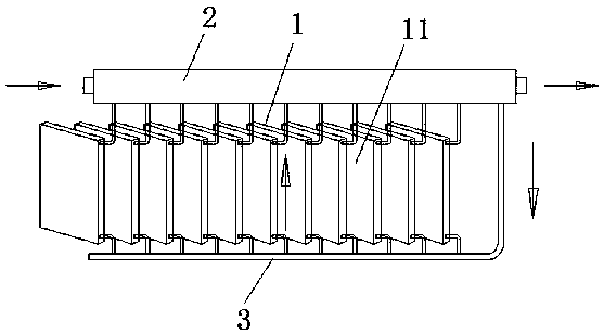
[0033] Such as image 3 As shown, in this embodiment, the phase change cooling system includes an evaporating part 1, a condensing part 2 and an evaporating and condensing pipeline 3; the evaporating and condensing pipeline 3 connects the evaporating part 1 and the condensing part 2 into a continuous circulation loop; Filled with liquid working fluid.
[0034] Specifically, the evaporating part 1 is composed of several heat-absorbing plates 11 arranged in an array and penetrated inside, the condensing part 2 is arranged on the top of the several heat-absorbing plates 11, and communicates with the several heat-absorbing plates 11, and the bottoms of the several heat-absorbing plates 11 pass through The evaporation and condensation pipeline 3 communicates with the condensing part 2, wherein the condensing part 2 is also a water condenser, and its structure is the same as that of the water condenser in Embodiment 1, so it will not be described again.
[0035] During specific ope...
PUM
 Abstract
Description
Claims
Application Information
 - R&D
- Intellectual Property
- Life Sciences
- Materials
- Tech Scout
- Unparalleled Data Quality
- Higher Quality Content
- 60% Fewer Hallucinations
Browse by: Latest US Patents, China's latest patents, Technical Efficacy Thesaurus, Application Domain, Technology Topic, Popular Technical Reports.
© 2025 PatSnap. All rights reserved.Legal|Privacy policy|Modern Slavery Act Transparency Statement|Sitemap|About US| Contact US: help@patsnap.com


