Limiting structure and pressure drop device

A limit structure and position limit technology, applied in the direction of valve device, valve housing structure, valve lift, etc., can solve problems such as processing difficulties and limit errors, and achieve simple and reasonable structural design, reduce limit errors, and ensure limit The effect of bit precision

Active Publication Date: 2016-08-24
GREE ELECTRIC APPLIANCES INC
View PDF5 Cites 0 Cited by
  • Summary
  • Abstract
  • Description
  • Claims
  • Application Information

AI Technical Summary

Problems solved by technology

However, the uppermost moving position and the lowermost moving position of the rotor part are realized by three parts: the lower limit part, the magnet and the valve flow channel, and the assembly accuracy is high, otherwise it is easy to cause a large limit error; and the magnet limit structure needs to be It is very difficult to process the inner cylindrical surface of the magnet

Method used


Image

  • Limiting structure and pressure drop device
  • Limiting structure and pressure drop device
  • Limiting structure and pressure drop device

Examples


Embodiment Construction

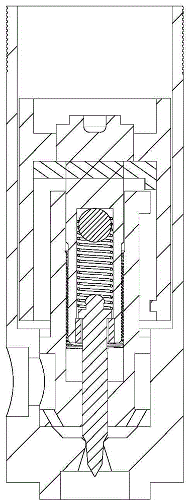
[0034] In order to make the objectives, technical solutions and advantages of the present invention more clearly understood, the limiting structure and the pressure drop device of the present invention will be further described in detail below through embodiments and in conjunction with the accompanying drawings. It should be understood that the specific embodiments described herein are only used to explain the present invention, but not to limit the present invention.

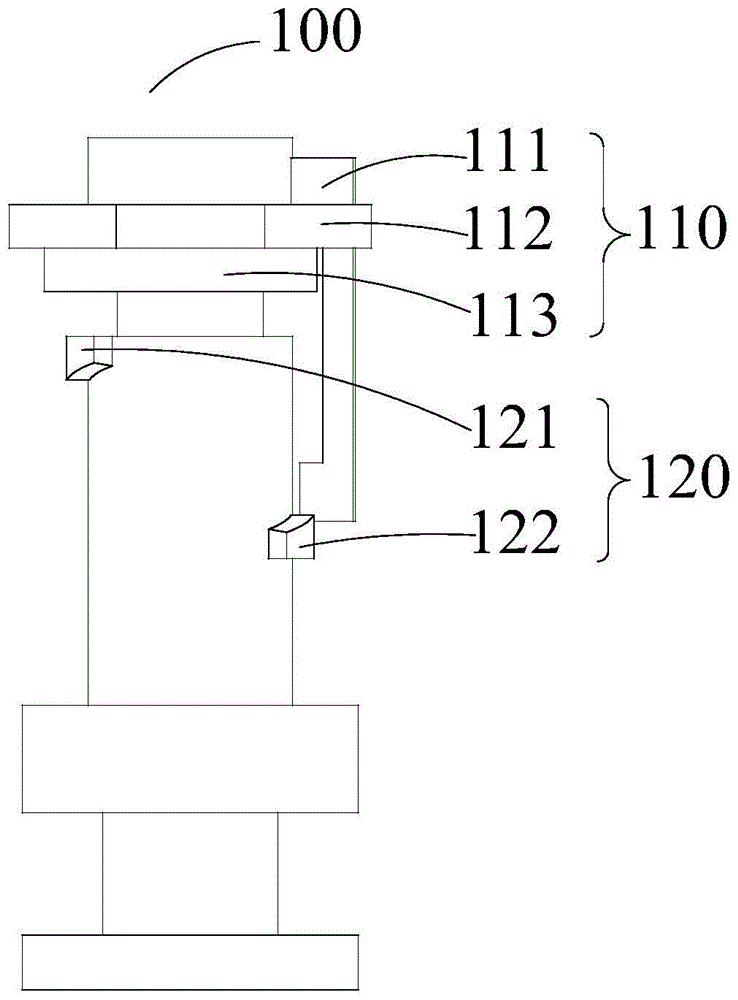
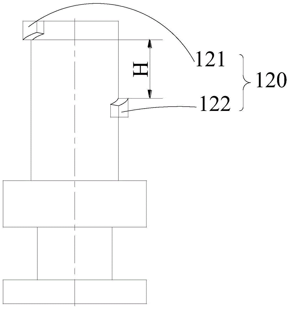
[0035] see Figure 2 to Figure 5 , the limit structure 100 of an embodiment includes a rotor part 110 and a valve flow channel part 120, the rotor part 110 is mounted on the valve flow channel part 120, and the rotor part 110 includes a sector limit part 111, an iron sheet 112 and a valve needle assembly 113, the iron piece 112 is installed on the valve needle assembly 113, the fan-shaped limiting part 111 is installed on the iron piece 112, the valve flow channel part 120 is provided with an upper limit piece...


PUM


Abstract

The invention provides a limit structure and a pressure drop device. The limit structure comprises a rotor part and a valve flowing channel part. The rotor part is installed on the valve flowing channel part, the rotor part comprises a fan-shaped limit part, an iron piece and a valve needle assembly, the iron piece is installed on the valve needle assembly, the fan-shaped limit part is installed on the iron piece, an upper limit piece and a lower limit piece are arranged on the valve flowing channel part, and the upper limit piece is located above the lower limit piece. The pressure drop device contains the limit structure. According to the limit structure and the pressure drop device, the rotor part is limited through the valve flowing channel part and the fan-shaped limit part together, the limit structure and the pressure drop device are convenient and accurate to install, and limit accuracy is ensured.

Description

technical field [0001] The present invention relates to the field of mechanical limit devices, in particular to a limit structure and a pressure drop device including the limit structure. Background technique [0002] Generally, the limiting structure in the pressure drop device is such as figure 1 As shown in the figure, the valve needle assembly, the lower limit part and the magnet are assembled as a whole, which is called the rotor part, and is connected with the valve flow channel to realize the up and down movement. The lowermost moving position of the rotor part is limited by the valve flow channel limit structure and the lower limit part, figure 1 The rotor part is in the lowermost moving position; the uppermost moving position of the rotor part is limited by the valve flow channel limiting structure and the magnet limiting structure. However, the uppermost moving position and the lowermost moving position of the rotor part are realized by three parts: the lower lim...

Claims


Application Information

Patent Timeline
Patent Type & Authority Patents(China)
IPC IPC(8): F16K1/00F16K1/32F16K27/02
CPCF16K1/00F16K1/32F16K27/02
Inventor 周军王继承庄嵘杨阳段向春周金冶张馨云
Owner GREE ELECTRIC APPLIANCES INC
Why Eureka
Try Eureka