Electronic transformer automatic debugging system

An electronic transformer, fully automatic technology, applied in the direction of instruments, measuring electrical variables, measuring devices, etc., can solve the problems of low output accuracy, increase in current, increase in boost time, and potential safety hazards, and reduce safety risks. , Improve the accuracy and calibration efficiency, and achieve the effect of automatic calibration

Active Publication Date: 2018-03-23
STATE GRID CORP OF CHINA +1
View PDF6 Cites 0 Cited by
  • Summary
  • Abstract
  • Description
  • Claims
  • Application Information

AI Technical Summary

Problems solved by technology

However, this verification method has the following problems: 1. Manual adjustment is used to control the standard source output, which has potential safety hazards and the output accuracy is not high
2. The outdated way of manually reading the data of the electronic transformer calibrator and recording it with a computer has the problem of increasing the current and boosting time due to the slow manual recording speed, which causes serious problems of cable heating

Method used


Image

  • Electronic transformer automatic debugging system
  • Electronic transformer automatic debugging system
  • Electronic transformer automatic debugging system

Examples


Embodiment Construction

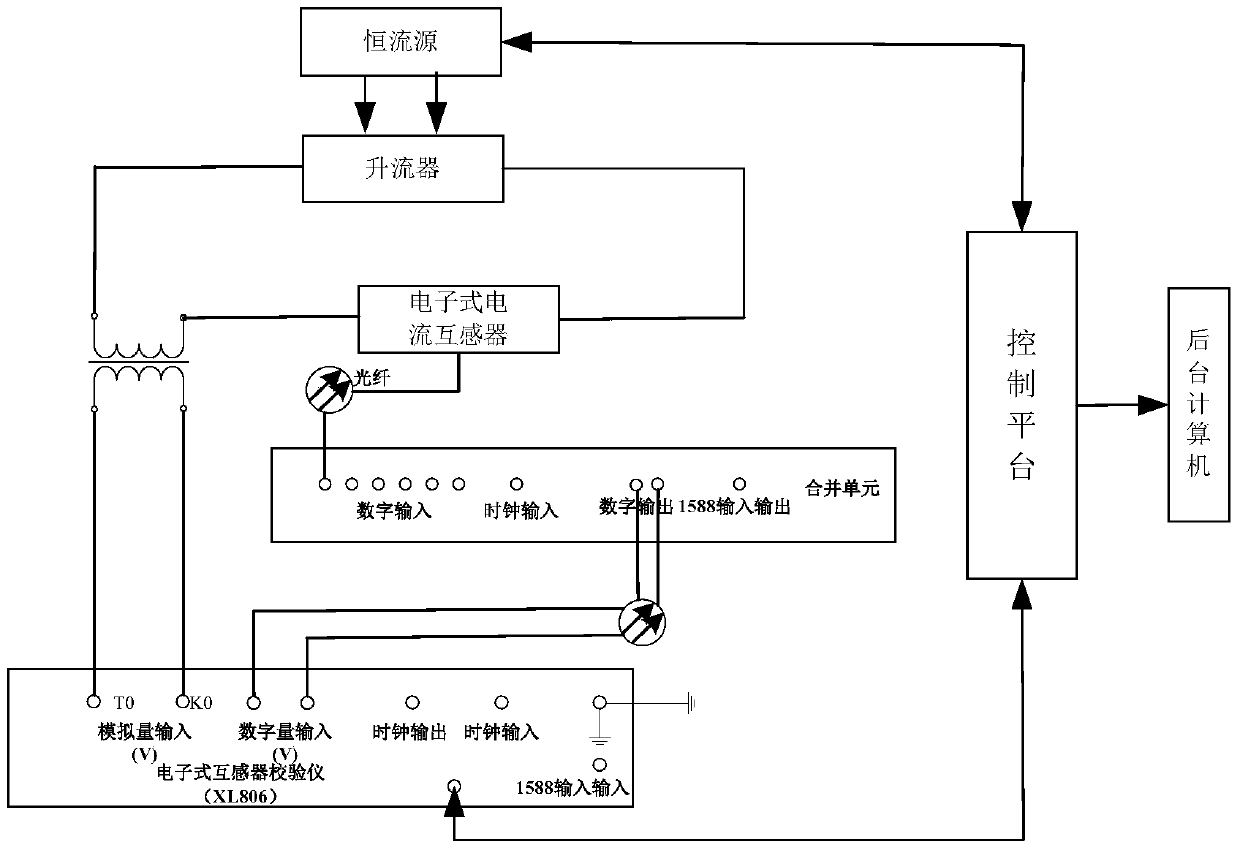
[0012] Such as figure 2 As shown in the figure, the electronic current transformer automatic debugging system, the primary side of the standard current transformer and the primary side of the electronic current transformer are connected in series to the output terminal of the current booster, and the input terminal of the current booster is connected to the constant current source output terminal. The output end of the standard current transformer is connected to the analog input end of the electronic transformer calibrator, the output end of the electronic current transformer is connected to the digital input end of the merging unit through an optical fiber, and the digital output end of the merging unit is connected through an optical fiber To the digital input terminal of the electronic transformer calibrator. The electronic transformer calibrator and constant current source are also connected to the control platform.

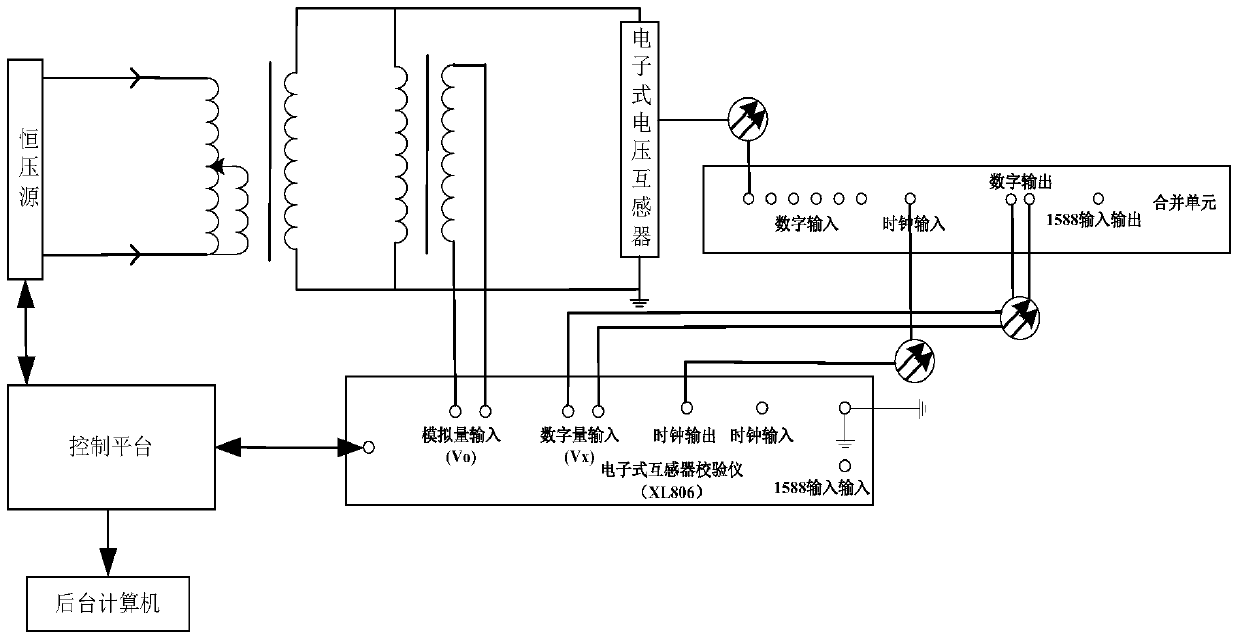
[0013] Such as image 3 As shown, the electronic v...


PUM


Abstract

Provided is an electronic transformer full-automatic debugging system. The input end of a standard transformer and the input end of a detected electronic transformer are simultaneously connected to the output end of a standard source, the output end of the standard transformer is connected to the analog quantity input end of an electronic transformer calibrator, the output end of the detected electronic transformer is connected to the digital input end of a merging unit through an optical fiber, and the digital output end of the merging unit is connected to the digital quantity input end of the electronic transformer calibrator through an optical fiber. The electronic transformer full-automatic debugging system comprises a control platform. The control platform comprises a DSP chip and a single-chip microcomputer which are connected. The DSP chip is connected with an Ethernet interface and a USB interface board. The Ethernet interface is connected with the electronic transformer calibrator, and the USB interface board is connected with a background computer. The single-chip microcomputer is connected with an RS232 interface which is connected with the control end of the standard source. By means of the electronic transformer full-automatic debugging system, calibration accuracy and calibration efficiency are improved, and the calibration security risk is greatly reduced.

Description

technical field [0001] The invention relates to the technical field of power system equipment calibration, in particular to a fully automatic debugging system for electronic transformers. Background technique [0002] At present, the test device used in the accuracy verification method of electronic transformer is composed of standard source, standard transformer, electronic transformer calibrator and related supporting equipment. The standard source generates a large current (high voltage), which is added to the primary side of the tested electronic transformer and the primary side of the standard transformer at the same time. The electronic transformer calibrator collects the analog output of the standard transformer as the standard value, and simultaneously passes The optical fiber collects the optical signal output of the electronic transformer from the merging unit as the tested value, and the calibrator automatically calculates the amplitude error and phase error of th...

Claims


Application Information

Patent Timeline
Patent Type & Authority Patents(China)
IPC IPC(8): G01R35/02
Inventor 刘彦琴刘翔宇王华陈绩唐广瑜杨红权董青迅胡祥胜
Owner STATE GRID CORP OF CHINA
Why Eureka
Try Eureka