
New aliphatic polyurethane paint mixing device

A technology of polyurethane and mixing device, which is applied in polyurea/polyurethane coatings, mixers, mixers with rotary stirring devices, etc., can solve problems such as damage to mixing kettles, unfavorable mixing, and insufficient mixing of paints. To achieve the effect of quality assurance

Inactive Publication Date: 2014-10-15
苏州多贝机械科技有限公司
View PDF5 Cites 1 Cited by
  • Summary
  • Abstract
  • Description
  • Claims
  • Application Information

AI Technical Summary

Problems solved by technology

[0002] The new aliphatic polyurethane paint mixing device is mainly used for mixing and toning the aliphatic polyurethane paint. The existing paint mixing device has a complex structure and single function, and is generally only placed along the inside of the paint mixing kettle. Rotating in one direction will cause the paint to be mixed unevenly, or make the color of the aliphatic paint color paste added to the mixing kettle mixed with the polyurethane paint in the kettle to be uneven, and because the paint generally has a certain viscosity The consistency makes it easy to stick to the inner wall of the paint mixing kettle during the mixing process. If it goes on for a long time, a thick layer of paint will accumulate on the wall of the kettle, which will not only waste raw materials, but also easily damage the paint. Mixing Kettle Causes Damage
[0003] At the same time, the existing paint mixing device lacks a liquid level monitoring device in the mixing tank, and the operator cannot observe the liquid level in the mixing tank in time, resulting in the phenomenon that more materials are added and it is difficult to mix, and even the material liquid refluxes.
Moreover, the aliphatic polyurethane paint needs to be mixed at a certain temperature to complete a good mixing process. When the temperature is low, it is not conducive to its mixing and affects the product quality.

Method used


Image

  • New aliphatic polyurethane paint mixing device

Examples


Embodiment Construction

[0013] In order to make the implementation technical means, creative features, objectives and effects of the present invention easy to understand, the present invention will be further elaborated below in conjunction with specific illustrations.

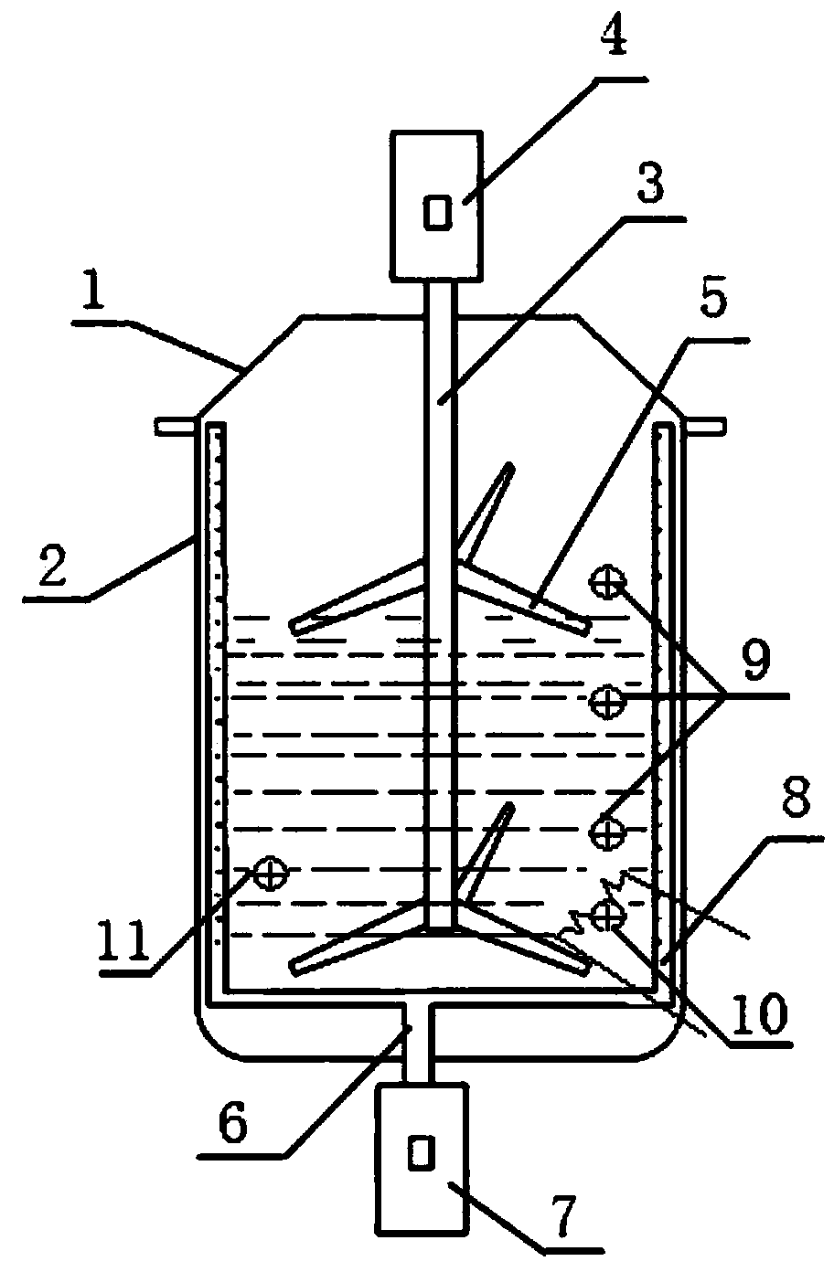
[0014] Such as figure 1 As shown, the new aliphatic polyurethane paint mixing device includes a kettle body 2 and a kettle cover 1 connected to the kettle body 2. A stirring shaft 3 is installed through the kettle cover 1, and the stirring shaft outside the kettle cover 1 3 is connected with a stirring motor 4, a stirring shaft 3 located in the kettle cover 1 is provided with a stirring paddle 5, and a runner 6 is also provided at the center of the bottom of the kettle body 2, and the runner 6 is connected with a A scraper 8 that rotates on the inner wall, the runner 6 is connected to the drive motor 7 outside the kettle body 2, a liquid level sensor 9, a heater 10 and a temperature sensor 11 are also arranged in the kettle body 2, t...


PUM


Abstract

The invention discloses an aliphatic polyurethane paint mixing device, which comprises a kettle and a kettle cover connected to the kettle. The aliphatic polyurethane paint mixing device is characterized in that a stirring shaft penetrates through the kettle cover, the stirring shaft outside the kettle cover is connected to a stirring motor, the stirring shaft inside the kettle cover is provided with a stirring paddle, a rotating wheel is arranged at the center of the bottom of the kettle, the rotating wheel is connected to a scraper which can rotate closely to the inner wall of the kettle, the rotating wheel is connected to a drive motor on the outer side of the kettle, and a liquid level sensor, a heater and a temperature sensor are also arranged in the kettle. According to the aliphatic polyurethane paint mixing device, the materials of the aliphatic polyurethane paint are uniformly mixed, residues on the kettle wall can be effectively cleared, situation of liquid level in the mixing kettle can be monitored in real time, meanwhile required temperature is provided for mixing the aliphatic polyurethane paint, and product quality is ensured.

Description

technical field [0001] The invention relates to the field of paint production equipment, in particular to a novel aliphatic polyurethane paint mixing device. Background technique [0002] The new aliphatic polyurethane paint mixing device is mainly used for mixing and toning the aliphatic polyurethane paint. The existing paint mixing device has a complex structure and single function, and is generally only placed along the inside of the paint mixing kettle. Rotating in one direction will cause the paint to be mixed unevenly, or make the color of the aliphatic paint color paste added to the mixing kettle mixed with the polyurethane paint in the kettle to be uneven, and because the paint generally has a certain viscosity The consistency makes it easy to stick to the inner wall of the paint mixing kettle during the mixing process. If it goes on for a long time, a thick layer of paint will accumulate on the wall of the kettle, which will not only waste raw materials, but also ea...

Claims


Application Information

Patent Timeline
Patent Type & Authority Applications(China)
IPC IPC(8): B01F7/18B01F15/00B01F15/06C09D175/04
Inventor 王宁
Owner 苏州多贝机械科技有限公司
Learn More