Hydraulic punching method and device capable of keeping wall flatness of workpiece

A punching device and flatness technology, which is applied in the field of hydraulic punching and devices for maintaining the flatness of the workpiece wall, can solve the problems of undisclosed technical means of forming hole quality, high internal pressure, etc., to reduce manufacturing costs and control difficulties, The effect of reducing thrust, improving flatness and precision

Active Publication Date: 2014-10-15
BAOSHAN IRON & STEEL CO LTD
View PDF8 Cites 11 Cited by
  • Summary
  • Abstract
  • Description
  • Claims
  • Application Information

AI Technical Summary

Problems solved by technology

[0004] However, this existing hydraulic punching process has disadvantages: hydraulic punching generally adopts the punching method from the outside to the inside, and uses high-pressure liquid as the support of the die. If the collapse is to be effectively prevented, the internal pressure P must be sufficiently high
Which does not reveal how to improve the quality of the forming hole technical means

Method used


Image

  • Hydraulic punching method and device capable of keeping wall flatness of workpiece
  • Hydraulic punching method and device capable of keeping wall flatness of workpiece
  • Hydraulic punching method and device capable of keeping wall flatness of workpiece

Examples


Embodiment Construction

[0036] In order to make the above objects, features and advantages of the present invention more comprehensible, specific implementations of the present invention will be described in detail below in conjunction with the accompanying drawings. First of all, it should be noted that the present invention is not limited to the following specific embodiments. Those skilled in the art should understand the present invention from the spirit embodied in the following embodiments, and each technical term can be optimized based on the spirit of the present invention. broad understanding. The same or similar components in the figures are denoted by the same reference numerals.

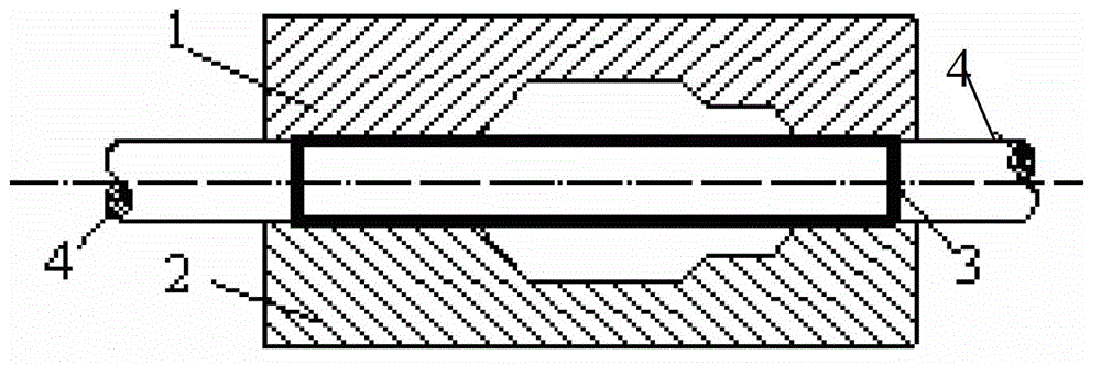
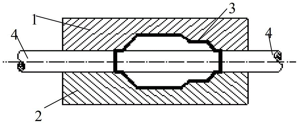
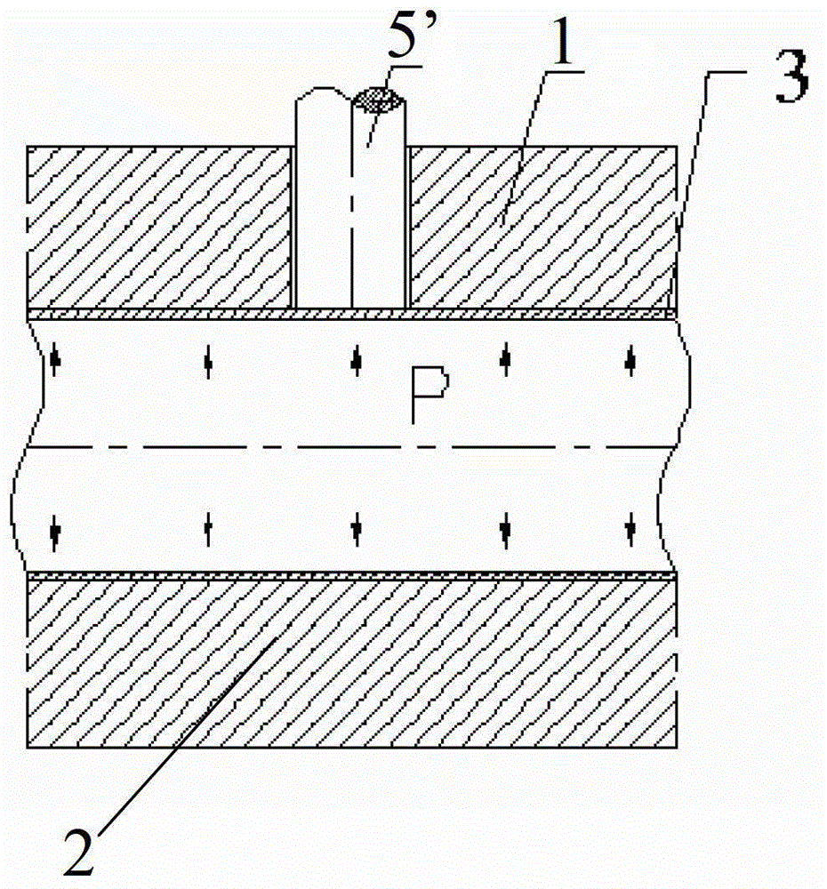
[0037] The present invention provides a hydraulic punching device and a hydraulic punching method, which can make the part of the workpiece, such as the pipe fitting 6 in this embodiment, that needs to be punched before punching in one working stroke of the hydraulic punching cylinder. Bulging, a certain amount...


PUM


Abstract

The invention relates to a hydraulic punching method and a hydraulic punching device capable of keeping wall flatness of a workpiece. The hydraulic punching device is arranged in a stepped cavity of an upper die body, wherein the stepped cavity comprises a first sub-cavity, a second sub-cavity, a third sub-cavity and a fourth sub-cavity, and the upper die body and a lower die body are matched to form a cavity for clamping the workpiece; the hydraulic punching device comprises a punching head body which is arranged in the first sub-cavity and the second sub-cavity, a transverse elastic sliding component which is arranged in the third sub-cavity and a piston ejector rod component which is arranged in the fourth sub-cavity and the punching head bodies in a penetrating way; the piston ejector rod component is elastically restrained and positioned by the transverse elastic sliding component; the punching head body moves upwards when the workpiece raises upwards under the effect of internal hydraulic pressure of the punching head body; the piston ejector rod component pushes the punching head body to move downwards to remove a raised part and form a punched hole when a piston is subjected to downward driving force. The hydraulic punching method and the hydraulic punching device capable of keeping the wall flatness of the workpiece have the advantages that since a punching rod is enabled to firstly move upwards and then move downwards to realize punching by using one punching stroke, a hole mouth is prevented from being collapsed, the flatness and the precision of the wall of a pipe are kept, and the hydraulic punching efficiency is improved.

Description

technical field [0001] The invention relates to a workpiece hydroforming method and device, in particular to a hydraulic punching method and device for workpiece hydroforming. Background technique [0002] In the fields of aircraft, spacecraft and automobiles, reducing weight to save materials and energy during operation is one of the trends in the development of modern manufacturing technology. Hydroforming is developed under this background as an advanced manufacturing technology for manufacturing hollow lightweight structural parts. This technology can not only improve the strength and rigidity of formed parts, but also save materials and reduce costs. The basic process of this technology is as follows Figure 1a and 1b Shown: as Figure 1a As shown, the pipe 3 is first placed in the lower die 2, then the upper die 1 is closed, the two ends of the pipe 3 are sealed with horizontal punches 4, 4, and the pipe 3 is filled with liquid; then, as Figure 1b As shown, in the p...

Claims


Application Information

Patent Timeline
Patent Type & Authority Applications(China)
IPC IPC(8): B21D26/035
Inventor 陈新平蒋浩民苏海波王娜
Owner BAOSHAN IRON & STEEL CO LTD
Why Eureka
Try Eureka