Scrap-collecting metal pipe cutting machine

A tube cutting machine and metal technology, which is applied to metal processing mechanical parts, metal processing equipment, pipe cutting devices, etc., can solve the problems of large waste of materials, low production efficiency, simple functions, etc., and achieve the effect of convenient use and simple structure.

Inactive Publication Date: 2014-10-15
南通市海门江海建设投资有限公司
View PDF10 Cites 14 Cited by
  • Summary
  • Abstract
  • Description
  • Claims
  • Application Information

AI Technical Summary

Problems solved by technology

Manual cutting is flexible and convenient, but the quality of manual cutting is poor, the size error is large, the material waste is large, and the follow-up processing workload is large. At the same time, the working conditions are harsh and the production efficiency is low. Due to the use of cutting molds, it is not suitable for cutting single pieces, small batches and large workpieces; although other types of semi-automatic cutting machines reduce the labor intensity of workers, their functions are simple and are only suitable for cutting parts with more regular shapes; CNC cutting is relatively manual Compared with the semi-automatic cutting method, it can effectively improve the efficiency and quality of plate cutting, and reduce the labor intensity of the operator.
Some small and medium-sized enterprises in our country even use manual cutting and semi-automatic cutting methods in some large enterprises. At present, there are still some problems in the cutting work of metal pipes, such as cutting metal pipes in batches, using manual cutting or Semi-automatic cutting has problems such as poor work efficiency and poor quality. In addition, in the process of cutting metal pipes, a large amount of metal debris will be generated. These debris will remain in the equipment for a long time, causing damage and pollution to the equipment. got a job

Method used


Image

  • Scrap-collecting metal pipe cutting machine
  • Scrap-collecting metal pipe cutting machine

Examples


Embodiment Construction

[0015] Specific embodiments of the present invention will be further described in detail below.

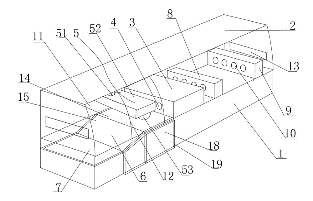
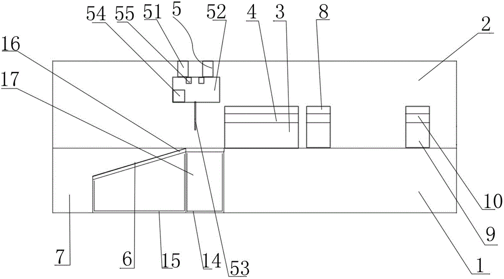
[0016] like figure 1 and figure 2 As shown, a chip-collecting metal pipe cutting machine of the present invention includes a rectangular block base 1 and a box body 2 arranged on the upper part of the base 1, and a guide device 3 is arranged in the center of the top of the base 1, and a guide device 3 is located at the center of the base 1. The top of the box body 2 on the side is provided with a cutting part 5, and the base 1 at the bottom of the cutting part 5 is provided with a first groove 14 sunken inward, and one side of the first groove 14 is provided with a second groove 15, and the second A slope 6 is provided on the top of the groove 15 , a layer of metal mesh 16 is provided on the slope 6 and the top of the first groove 14 , and a collection box 7 is arranged on one side of the second groove 15 .

[0017] When the metal pipe is cut off, a large amount of metal debris...


PUM


Abstract

The invention discloses a scrap-collecting metal pipe cutting machine, which comprises a rectangular block base and a box arranged on the upper part of the base. The scrap-collecting metal pipe cutting machine is characterized in that a clockwise guide device is arranged in the center of the top of the base; a cutting part is arranged on the top of the box, on one side of the clockwise guide device; an inwards-indented first groove is formed in the base, on the lower part of the cutting part; a second groove is arranged on one side of the first groove; a slope is arranged on the top of the second groove; the top of the slope and the top of the first groove are respectively provided with a layer of metal mesh. According to the scrap-collecting metal pipe cutting machine, the first and second grooves are used for collecting the metal scraps, the slope is arranged on the top of the second groove, thus a metal pipe can enter the collecting box besides the second groove, the top of the slope and the top of the first groove are respectively provided with one layer of metal mesh, adapting of the metal pipe is facilitated, and the metal scraps can also enter the grooves. The scrap-collecting metal pipe cutting machine has the advantages of simple structure, convenience in use and the like.

Description

technical field [0001] The invention relates to a cutting machine, in particular to a chip-collecting metal pipe cutting machine. Background technique [0002] With the development of the modern mechanical processing industry, the requirements for cutting quality and precision are constantly improving, and the requirements for improving production efficiency, reducing production costs, and highly intelligent automatic cutting functions are also increasing. In the process of mechanical processing, the common methods of plate cutting include manual cutting, semi-automatic cutting machine cutting and CNC cutting machine cutting. Manual cutting is flexible and convenient, but the quality of manual cutting is poor, the size error is large, the material waste is large, and the follow-up processing workload is large. At the same time, the working conditions are harsh and the production efficiency is low. Due to the use of cutting molds, it is not suitable for cutting single pieces...

Claims


Application Information

Patent Timeline
Patent Type & Authority Applications(China)
IPC IPC(8): B23D21/00B23Q11/00
Inventor 宋环
Owner 南通市海门江海建设投资有限公司
Why Eureka
Try Eureka