Kayak

A technology for kayaks and hulls, which is applied to ships, ship parts, and pipelines for emptying/ballasting, etc. It can solve the problems of athletes' competition interference, increase the weight of kayaks, and athletes' discomfort, and achieve drainage performance Stable, high drainage efficiency

Inactive Publication Date: 2014-10-15
叶如康
View PDF1 Cites 3 Cited by
  • Summary
  • Abstract
  • Description
  • Claims
  • Application Information

AI Technical Summary

Problems solved by technology

[0002] With the continuous popularization of kayak sports, its competitive level continues to improve. In high-level competitions, such as Olympic Games, details often determine success or failure. As we all know, water droplets often enter the inner compartment of kayaks during sliding, which brings There are two problems, one is to cause discomfort to the athletes, and the other is to increase the weight of the kayak itself. Since the Olympic Committee clearly stipulates that non-human machinery and equipment cannot be installed on the kayak, the drainage of the kayak’s interior compartment has become a big problem. The application The Chinese patent No. 200820165360.7 has made beneficial improvements, disclosing a new type of kayak with self-drainage function, which includes a boat cover and a boat bottom, and the boat cover and boat bottom are combined to form a double-hull hull, boat cover and boat bottom A buoyancy chamber is formed between them. The kayak is equipped with a drainage hole at the lowest point of the kayak inner cabin, which has a self-drainage function and can use the principle of inertia to automatically discharge the accumulated water in the kayak from the drainage hole when the kayak moves forward. outboard
However, this technology still has some disadvantages. It is very risky to set the drainage hole at the lowest point of the kayak inner cabin. Once the whole set of devices goes wrong during operation, the water will pour back from the drainage hole and cause major interference to the athletes’ competition. Secondly, use the principle of inertia Drainage is not efficient through weep holes

Method used


Image

  • Kayak
  • Kayak
  • Kayak

Examples


Embodiment 1

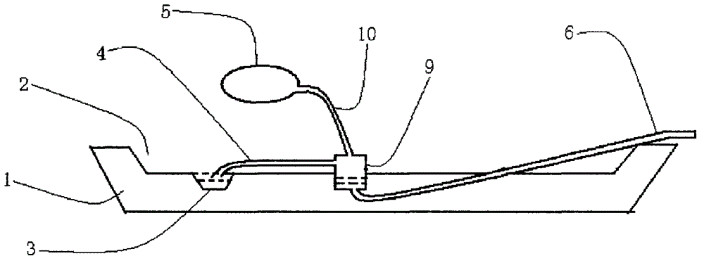
[0022] A kayak, comprising a hull 1, where the hull 1 is used to accommodate contestants to form an inner cabin 2, where the inner cabin 2 is prone to water accumulation to form a low-lying water accumulation 3, and also includes a suction pipe 4, an airbag 5, A drainage pipe 6, a liquid collecting chamber 9, and a trachea 10; the airbag 5 can reset itself after being flattened, so that the airbag 5 is compressed when it is stressed, and self-expands when the stressed state is released; The location makes it possible to realize: during the gliding process of the kayak, the compressed and self-expanded motion states of the airbag 5 alternately appear; ; One end of the drain pipe 6 is connected to the bottom of the liquid collection chamber 9, and the other end extends to the outside of the hull 1;

[0023] Wherein, the airbag 5 is arranged on the inside of the player's calf root.

[0024] The solution of the present invention is realized in this way: during the competition, si...

Embodiment 2

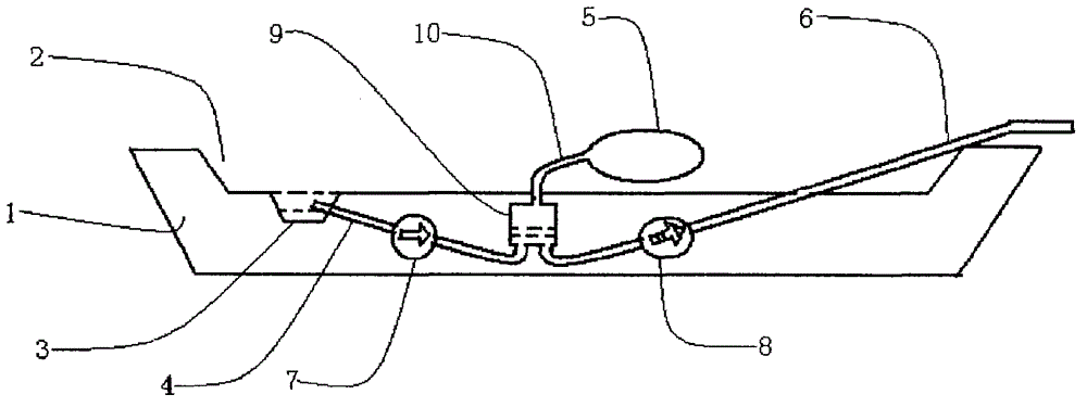
[0026] A kayak, comprising a hull 1, where the hull 1 is used to accommodate contestants to form an inner cabin 2, where the inner cabin 2 is prone to water accumulation to form a low-lying water accumulation 3, and also includes a suction pipe 4, an airbag 5, A drainage pipe 6, a liquid collecting chamber 9, and a trachea 10; the airbag 5 can reset itself after being flattened, so that the airbag 5 is compressed when it is stressed, and self-expands when the stressed state is released; The location makes it possible to realize: during the gliding process of the kayak, the compressed and self-expanded motion states of the airbag 5 alternately appear; ; One end of the drain pipe 6 is connected to the bottom of the liquid collection chamber 9, and the other end extends to the outside of the hull 1;

[0027] Among them, a first check valve 7 is also included. The first check valve 7 is arranged in the suction pipe 4 . The first check valve 7 is used to prevent the fluid in the li...

Embodiment 3

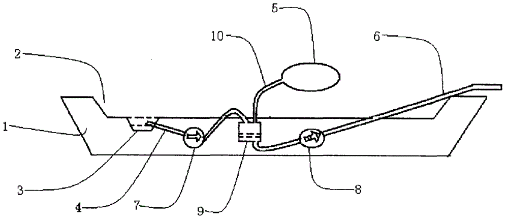
[0036] A kayak, comprising a hull 1, where the hull 1 is used to accommodate contestants to form an inner cabin 2, where the inner cabin 2 is prone to water accumulation to form a low-lying water accumulation 3, and also includes a suction pipe 4, an airbag 5, A drainage pipe 6, a liquid collecting chamber 9, and a trachea 10; the airbag 5 can reset itself after being flattened, so that the airbag 5 is compressed when it is stressed, and self-expands when the stressed state is released; The location makes it possible to realize: during the gliding process of the kayak, the compressed and self-expanded motion states of the airbag 5 alternately appear; ; One end of the drain pipe 6 is connected to the bottom of the liquid collection chamber 9, and the other end extends to the outside of the hull 1;

[0037] Among them, a first check valve 7 is also included. The first check valve 7 is arranged in the suction pipe 4 . The first check valve 7 is used to prevent the fluid in the li...


PUM


Abstract

Compared with the prior art, the scheme of the invention relates to a kayak, which comprises a kayak body, the place, which is used for containing an athlete, of the kayak body is formed into an interior, a low-lying water accumulation place is formed at the place, in which water can be easily accumulated, of the interior, and the kayak also comprises a sucker, an air bag, a drain tube, a liquid accumulation chamber and an air tube; after being squashed, the air bag can be self-restored, so the air bag can be compressed when stressed, and can be self-expanded after stress is removed; due to the position of the air bag, the air bag can be alternately compressed and self-expanded in the sliding process of the kayak; the front end of the sucker is connected with the low-lying water accumulation place, and the tail end of the sucker is connected with the liquid accumulation chamber; one end of the drain tube is connected with the bottom of the liquid accumulation chamber, and the other end of the drain tube stretches out of the kayak body; the front end of the air tube is connected with the liquid accumulation chamber, and the tail end of the liquid accumulation chamber is connected with the air bag. The scheme of the invention has the following advantages that water can be drained as the kayak advances, moreover, the drainage efficiency is high, and the drainage performance is stable.

Description

technical field [0001] The proposal of the invention relates to the field of kayak manufacture. Background technique [0002] With the continuous popularization of kayak sports, its competitive level continues to improve. In high-level competitions, such as Olympic Games, details often determine success or failure. As we all know, water droplets often enter the inner compartment of kayaks during sliding, which brings There are two problems, one is to cause discomfort to the athletes, and the other is to increase the weight of the kayak itself. Since the Olympic Committee clearly stipulates that non-human machinery and equipment cannot be installed on the kayak, the drainage of the kayak’s interior compartment has become a big problem. The application The Chinese patent No. 200820165360.7 has made beneficial improvements, disclosing a new type of kayak with self-drainage function, which includes a boat cover and a boat bottom, and the boat cover and boat bottom are combined t...

Claims


Application Information

Patent Timeline
Patent Type & Authority Applications(China)
IPC IPC(8): B63B13/00
Inventor 叶如康
Owner 叶如康
Why Eureka
Try Eureka