
Foundation pit supporting structure and construction method thereof

A technology for foundation pit support and foundation pit, which is applied in foundation structure engineering, excavation, sheet pile wall, etc.

Active Publication Date: 2021-01-26
东莞市建安桩基础工程有限公司
View PDF7 Cites 5 Cited by
  • Summary
  • Abstract
  • Description
  • Claims
  • Application Information

AI Technical Summary

Problems solved by technology

[0004] In view of the above-mentioned related technologies, the inventor believes that the accumulated water in the outlet tank is pumped out through the drainage pump to complete the drainage of the foundation pit. Generally, this method can only drain the bottom of the foundation pit, and there is also a certain accumulation on the side wall of the foundation pit. However, the accumulated water on the side wall of the foundation pit cannot be discharged. When the groundwater level is higher than the bottom of the foundation pit, the side wall of the foundation pit also bears a large lateral pressure, which may easily lead to the collapse of the side wall of the foundation pit.

Method used


Image

  • Foundation pit supporting structure and construction method thereof
  • Foundation pit supporting structure and construction method thereof
  • Foundation pit supporting structure and construction method thereof

Examples


Embodiment Construction

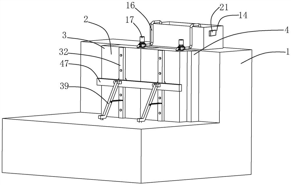
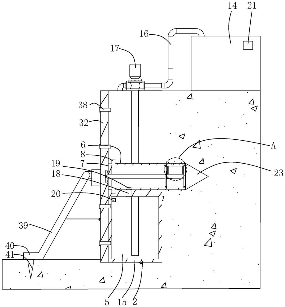
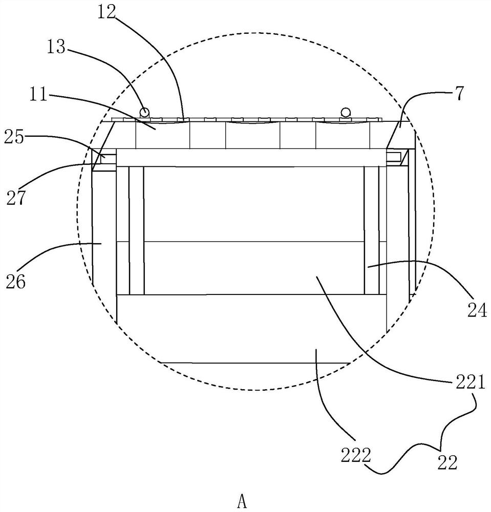
[0043] The following is attached Figure 1-8 The application is described in further detail.

[0044] The embodiment of the application discloses a foundation pit supporting structure and a construction method thereof. refer to figure 1 , a support structure for a foundation pit 1, including a foundation pit 1 and a plurality of protective plates 2 spliced ​​with each other. A first splicing block 3 and a second splicing block 4 are respectively integrally formed at opposite ends of two adjacent protective plates 2 , and both the first splicing block 3 and the second splicing block 4 are arranged along the length direction of the protective plate 2 . The first splicing block 3 is spliced ​​and matched with the second splicing block 4, so as to facilitate the positioning and installation of the protective plate 2.

[0045] refer to figure 2 The side surface of the protective plate 2 attached to the side wall of the foundation pit 1 is provided with a through-groove 6 arran...


PUM


Abstract

The invention relates to the field of foundation pit supporting, in particular to a foundation pit supporting structure and a construction method thereof. According to the specific scheme, the foundation pit supporting structure comprises a foundation pit and a plurality of mutually-spliced protection plates, each protection plate is provided with a supporting pipe, one side wall of each protection plate is provided with a through groove for containing the corresponding supporting pipe, and the supporting pipes are detachably connected into the through grooves. A plurality of water seepage holes are formed in the ends, extending out of the through grooves, of the supporting pipes, adjusting assemblies used for adjusting the water seepage amount of the water seepage holes are arranged in the supporting pipes, the two ends of the supporting pipes are both closed ends, a drainage cavity is formed in each protection plate and located in the lower portion of each through groove, the throughgrooves and the drainage cavities communicate with communicating holes, and drainage holes are formed in one sides of the supporting pipes. The drainage holes communicate with the communicating holes, a water storage tank is arranged on the foundation pit, a water suction pump is arranged in the end, away from the bottom of the foundation pit, of each protection plate, drainage pipes are arrangedbetween the water suction pumps and the water storage tank in a communicating mode, and water suction pipes are arranged between the water suction pumps and the drainage cavities in a communicating mode.

Description

technical field [0001] The present application relates to the field of foundation pit support, in particular to a foundation pit support structure and a construction method thereof. Background technique [0002] With the rapid development of the modern construction industry, there are more and more high-rise and super high-rise buildings. Due to the load on the upper part of high-rise and super high-rise buildings, most of them adopt compensatory foundations. The buried depth is large, and the excavation of the foundation pit is deep, especially when the deep foundation pit is excavated in the area with a high groundwater level, the soil aquifer will be cut off, and the groundwater will continue to seep into the foundation pit, causing quicksand, slope instability or foundation bearing power down. [0003] An existing deep foundation pit drainage structure includes the outer wall of the deep foundation pit, the inner wall of the deep foundation pit outer wall is provided wi...

Claims


Application Information

Patent Timeline
IPC IPC(8): E02D17/04E02D5/76E02D19/06
CPCE02D17/04E02D5/76E02D19/06
Inventor 杜耀辉
Owner 东莞市建安桩基础工程有限公司
Learn More