Driving mechanism for thread sewing and presser foot lifting thread-scissoring and buttonholing machine
A driving mechanism and presser foot lifting technology are applied to the thread cutting mechanism, cloth pressing mechanism, sewing machine components and other directions in the sewing machine, which can solve the problems of difficulty in operation and low efficiency, and achieve reduced labor intensity, high degree of automation, and shortened connection. effect of time
- Summary
- Abstract
- Description
- Claims
- Application Information
AI Technical Summary
Problems solved by technology
Method used
Image

Examples
Embodiment Construction
[0051] The implementation of the present invention will be illustrated by specific specific examples below, and those skilled in the art can easily understand other advantages and effects of the present invention from the contents disclosed in this specification.
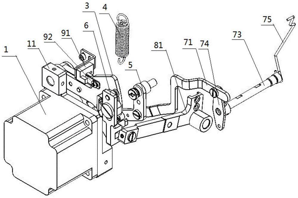
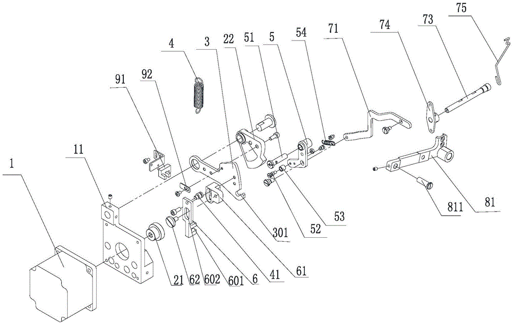
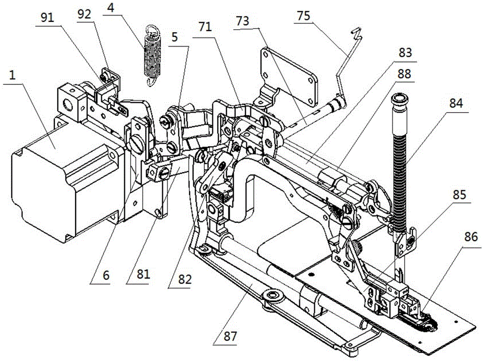
[0052] see Figure 1 to Figure 3 . It should be noted that the structures, proportions, sizes, etc. shown in the drawings attached to this specification are only used to match the content disclosed in the specification, for those who are familiar with this technology to understand and read, and are not used to limit the implementation of the present invention. Limiting conditions, so there is no technical substantive meaning, any modification of structure, change of proportional relationship or adjustment of size, without affecting the effect and purpose of the present invention, should still fall within the scope of the present invention. The disclosed technical content must be within the scope covered. At the sa...
PUM
 Abstract
Description
Claims
Application Information