
engine exhaust gas recirculation

An exhaust gas recirculation and exhaust gas recirculation valve technology, applied in engine components, engine control, combustion engine, etc., can solve the problems of EGR gas flow error, opening deviation, etc., to prevent exhaust emission, appropriate target opening, Effectively correcting the effect of target opening

Inactive Publication Date: 2016-08-17
AISAN IND CO LTD
View PDF9 Cites 0 Cited by
  • Summary
  • Abstract
  • Description
  • Claims
  • Application Information

AI Technical Summary

Problems solved by technology

The actual opening of the EGR valve deviates from the expected target opening due to the displacement of the spool, resulting in an error in the EGR gas flow

Method used


Image

  • engine exhaust gas recirculation
  • engine exhaust gas recirculation
  • engine exhaust gas recirculation

Examples


Embodiment Construction

[0036] Hereinafter, an embodiment of an exhaust gas recirculation device for an engine according to the present invention will be described in detail with reference to the drawings.

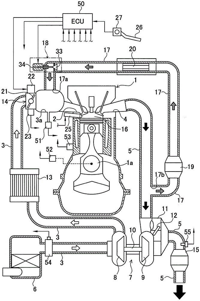
[0037] figure 1 An engine system with a supercharger including an exhaust gas recirculation device (EGR device) of the engine according to the present embodiment is shown by a schematic configuration diagram. The engine system includes a reciprocating engine 1 . The intake port 2 of the engine 1 is connected with an intake passage 3 , and the exhaust port 4 is connected with an exhaust passage 5 . An air filter 6 is provided at the inlet of the intake passage 3 . A supercharger 7 is provided on the intake passage 3 downstream of the air filter 6, and the supercharger 7 is used to carry out intake air in the intake passage 3 between the intake passage 3 and the exhaust passage 5. Boost.

[0038] The supercharger 7 includes a compressor 8 arranged in the intake passage 3 , a turbine 9 arranged...


PUM


Abstract

An EGR apparatus includes an EGR passage to allow part of exhaust gas discharged from a combustion chamber to flow in an intake passage and recirculate back to the combustion chamber and an EGR valve to regulate EGR gas in the EGR passage. The EGR valve includes a valve seat, a valve element, and a step motor. An ECU calculates a target correction value corresponding to an operating condition of an engine, cuts off energization to the step motor in order to hold the EGR valve at a predetermined opening degree during operation thereof, and then restarts energization to the step motor, calculates an energization cutoff correction value corresponding to an elapsed time from energization cutoff, and corrects the target correction value by the calculated energization cutoff correction value in order to control the EGR valve to the target opening degree.

Description

technical field [0001] The present invention relates to an exhaust gas recirculation device for an engine that causes a part of exhaust gas discharged from an engine to an exhaust passage to flow into an intake passage as exhaust recirculation gas, and to flow back to the engine. Background technique [0002] Conventionally, this technique has been applied to, for example, automobile engines. The exhaust gas recirculation device (Exhaust Gas Recirculation (EGR) device) guides part of the combusted exhaust gas discharged from the combustion chamber of the engine to the exhaust passage as EGR gas to the intake passage through the EGR passage, and is connected to the intake passage in the intake passage. The flowing intake air is mixed and returned to the combustion chamber. The EGR gas flowing through the EGR passage is regulated by an EGR valve provided in the EGR passage. This EGR can mainly reduce nitrogen oxides (NOx) in the exhaust gas, and improve fuel consumption at t...

Claims


Application Information

Patent Timeline
Patent Type & Authority Patents(China)
IPC IPC(8): F02D41/00F02M26/54
CPCF02D41/0077F02D2011/104F02D2041/2024F02M26/05F02M26/54Y02T10/40
Inventor 秋田实吉冈卫
Owner AISAN IND CO LTD
Learn More