Fast multi-direction multifunctional liquid control valve

A hydraulic control valve, multi-functional technology, applied in the field of hydraulic valves, can solve the problems of slow movement, long response time of hydraulic control valves, etc., and achieve the effects of rapid response, rapid reciprocating action control, and sensitive action

Inactive Publication Date: 2014-10-15
NINGBO JIANGDONG CHENGCHUANG IND PROD DESIGN CO LTD +1
View PDF8 Cites 8 Cited by
  • Summary
  • Abstract
  • Description
  • Claims
  • Application Information

AI Technical Summary

Problems solved by technology

[0005] In the above electromagnetic pilot valve, since the pilot valve and the main valve have the same spool structure, opening the main val...

Method used


Image

  • Fast multi-direction multifunctional liquid control valve
  • Fast multi-direction multifunctional liquid control valve
  • Fast multi-direction multifunctional liquid control valve

Examples


Embodiment Construction

[0039] The above and other technical features and advantages of the present invention will be described in more detail below in conjunction with the accompanying drawings.

[0040] The hydraulic control valve in the present invention drives the valve core to move up and down by controlling the fluid pressure difference between the upper and lower ends of the valve core to complete the opening and closing actions.

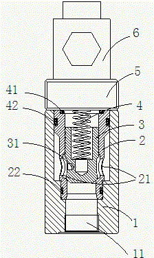
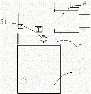
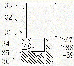
[0041] see figure 1 As shown, it is a schematic cross-sectional structure diagram of the fast multi-directional multi-functional hydraulic control valve of the present invention. The hydraulic control valve of the present invention includes a valve body 1, a valve sleeve 2, a valve core 3, and a valve seat 5, wherein the valve sleeve 2 is arranged on Inside the valve body 1 , the valve core 3 is arranged in the valve sleeve 2 , and the valve seat 5 is fixed on the upper end of the valve body 1 .

[0042] A main oil inlet 11 is provided at the bottom of the valve bo...


PUM


Abstract

The invention relates to a fast multi-direction multifunctional liquid control valve which comprises a valve element, a valve body and a valve seat. The valve element is disposed in the inner cavity of the valve body. The valve seat is fixed at the upper end of the valve body. A differential hole allowing the upper and lower ends of the valve element to generate differential pressure is formed in the valve element. A control hole is formed in the valve seat. The differential hole, the upper cavity of the valve element and the control hole are communicated. When a hydraulic valve opens, hydraulic oil in a main oil channel passes the differential hole, the upper cavity of the valve element and the control hole to form an oil channel; when the control hole is closed, the valve element moves under the action of the high-pressure hydraulic oil of the upper cavity of the valve element, and the liquid control valve is closed. The liquid control valve provided with the differential hole is fast and flexible in response, and pressure maintaining can be achieved.

Description

technical field [0001] The invention relates to the field of hydraulic valves, in particular to a fast multi-directional multifunctional hydraulic control valve. [0002] Background technique [0003] In the prior art, the electro-hydraulic control reversing valve is composed of a main valve and an electromagnetic pilot valve. The electromagnetic pilot valve is the pilot stage of the reversing main valve. Through electromagnetic operation or manual operation, the pilot valve and the main valve are connected together. In the main oil circuit, the opening pressure of the pilot valve and the main valve are different, or the opening sequence is different. However, the pilot valve and the main valve often have the same or similar structure. When opening the main valve, the pilot valve must be opened first. After the spool or piston of the pilot valve completes the corresponding moving stroke, it reaches the preset opening pressure. The core is turned on. [0004] Chinese paten...

Claims


Application Information

Patent Timeline
IPC IPC(8): F15B13/02
Inventor 涂雪龙
Owner NINGBO JIANGDONG CHENGCHUANG IND PROD DESIGN CO LTD
Why Eureka
Try Eureka