Defending instrument with catapulting mechanism
A device and machine body technology, applied in the field of electric shock devices with a single rope, can solve the problems of no ejection device, inability to shrink the harness rod, inconvenient storage and carrying, etc., and achieve the effects of convenient storage and portability, wide application and convenient operation
- Summary
- Abstract
- Description
- Claims
- Application Information
AI Technical Summary
Problems solved by technology
Method used
Image
Examples
Embodiment 1
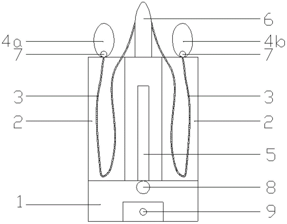
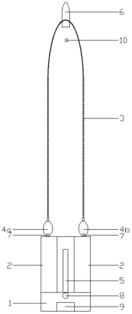
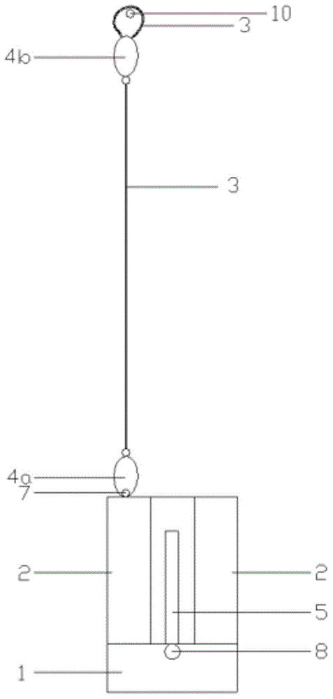
[0014] Embodiment 1: as figure 1 As shown, a defense device with an ejection mechanism includes a body 1, a rope box 2, a rope 3, a rope loop 4a, a rope loop 4b, an ejection mechanism 5, a warhead 6, a buckle 7, and an ejection button 8, and is characterized in that: The rope box 2 is installed on both sides of the body 1, the ejection mechanism 5 is installed in the middle of the body 1, the rope ring 4a and the rope ring 4b are connected to the body 1 through a buckle 7, the middle of the rope 3 is connected to the bullet 6, and the middle of the rope 3 is connected to the body 1. The tail end is connected with the loop 4 a and the loop 4 b, and the ejection mechanism 5 is connected with the ejection button 8 .
Embodiment 2
[0015] Embodiment 2: as figure 1 As shown, a defense device with an ejection mechanism includes a body 1, a rope box 2, a rope 3, a rope loop 4a, a rope loop 4b, an ejection mechanism 5, a warhead 6, a buckle 7, an ejection button 8, and a high-voltage pulse device 9 It is characterized in that: the rope box 2 is installed on both sides of the body 1, the ejection mechanism 5 is installed in the middle of the body 1, the rope loop 4a and the rope loop 4b are connected to the body 1 through a buckle 7, and the middle of the rope 3 is connected to the warhead 6. The tail end of the rope 3 is connected to the rope loop 4a and the rope loop 4b, the ejection mechanism 5 is connected to the ejection button 8, the high-voltage pulse device 9 is installed at the lower end of the body 1, and the high-voltage pulse device 9 has a bare wire power line on the rope 3. Winding, energized through the control power line of the power switch on the high-voltage pulse device.
Embodiment 3
[0016] Embodiment 3: as figure 1 As shown, a defense device with an ejection mechanism includes a body 1, a rope box 2, a rope 3, a rope loop 4a, a rope loop 4b, an ejection mechanism 5, a warhead 6, a buckle 7, and an ejection button 8, and is characterized in that: The rope box 2 is installed on both sides of the body 1, the ejection mechanism 5 is installed in the middle of the body 1, the rope ring 4a and the rope ring 4b are connected to the body 1 through a buckle 7, the middle of the rope 3 is connected to the bullet 6, and the middle of the rope 3 is connected to the body 1. The tail end is connected with the rope loop 4a and the rope loop 4b, and the ejection mechanism 5 is connected with the ejection button 8, the ejection mechanism 5 is configured as a bow, and the projectile 6 is configured as an arrow.
PUM
 Abstract
Description
Claims
Application Information
 - R&D
- Intellectual Property
- Life Sciences
- Materials
- Tech Scout
- Unparalleled Data Quality
- Higher Quality Content
- 60% Fewer Hallucinations
Browse by: Latest US Patents, China's latest patents, Technical Efficacy Thesaurus, Application Domain, Technology Topic, Popular Technical Reports.
© 2025 PatSnap. All rights reserved.Legal|Privacy policy|Modern Slavery Act Transparency Statement|Sitemap|About US| Contact US: help@patsnap.com


