Device and method for detecting surface defect on strip steel

A defect detection and strip technology, applied in the direction of optical testing flaws/defects, etc., can solve problems such as imaging technology not involved in the visual inspection system, and achieve the effect of improving the detection effect and avoiding the impact.

Active Publication Date: 2014-10-15
BAOSHAN IRON & STEEL CO LTD
View PDF10 Cites 18 Cited by
  • Summary
  • Abstract
  • Description
  • Claims
  • Application Information

AI Technical Summary

Problems solved by technology

None of these patents involves the imaging technology of the measured object of the visual inspection system in the harsh steel production environment

Method used


Image

  • Device and method for detecting surface defect on strip steel
  • Device and method for detecting surface defect on strip steel
  • Device and method for detecting surface defect on strip steel

Examples


Embodiment 1

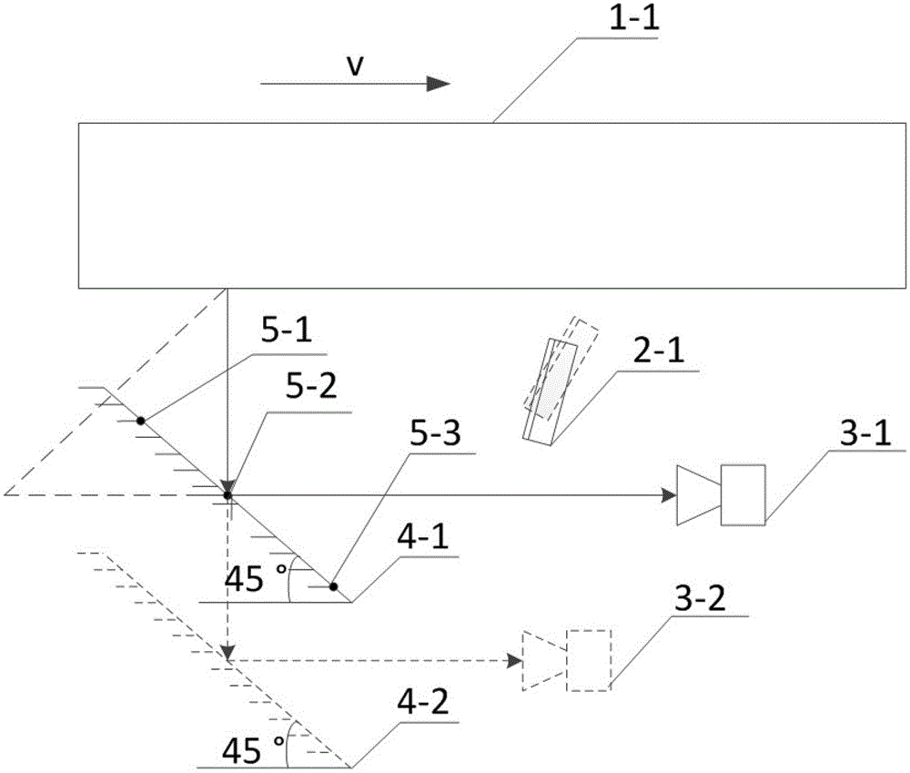
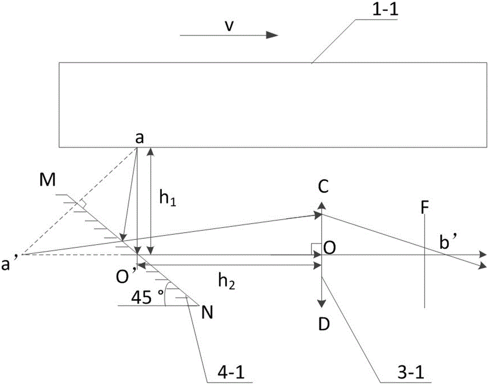
[0052] Such as image 3 As shown, according to the pre-calculated imaging distance H, and according to the actual conditions of the lower surface space on site, the vertical distance h of the lower surface is calculated 1 , and calculate the horizontal distance h at the same time 2 =H-h 1 . Arrange the position of the reflector 4-1 and its CCD camera 3-1 of the steel lower surface 1-1 according to this distance, such as figure 1 shown. Determine the illumination mode of the light source (bright field illumination or dark field illumination) according to the previous experimental plan, and determine the illumination angle of the light source 2-1.

[0053] First, according to Figure 5 The flow automatically adjusts the illumination of the light source, and then the CCD camera 3-1 will obtain the strip steel information through the imaging reflector 4-1. The surface morphology of the steel strip is the surface morphology of the steel strip obtained after being reflected by...

Embodiment 2

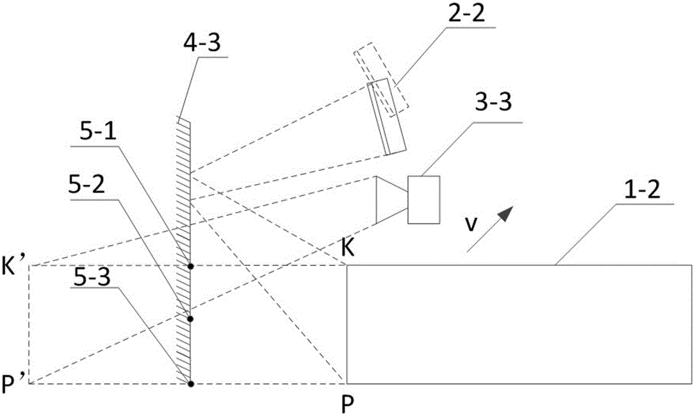
[0056] Such as figure 2 As shown, first determine the lighting position of the light source according to the image acquisition position and the actual side space position of the thick plate on site, and arrange the position of the light source 2-2 and the position of the light source reflector 4-3. Calculate the imaging distance according to the preset resolution, and arrange the positions of CCD cameras 3-3.

[0057] according to Figure 5 The flow automatically adjusts the illumination of the light source, and then the CCD camera 3-3 will obtain the steel strip information through the imaging reflector 4-3. At the same time, the light source 2-2 illuminates the defective surface through the reflector 4-3, and the equipped angle adjustment mechanism can adjust the angle of the light source at any time to ensure the matching of the lighting mode. The quality of the images collected by the CCD camera 3-3 can also reflect the cleanliness of the mirror surface in time. Once th...


PUM


Abstract

The invention discloses a device and a method for detecting surface defects on a strip steel. The method includes following steps: arranging a plain mirror on a to-be-detected surface of the strip steel or a thick plate, wherein the plain mirror and the to-be-detected surface are arranged at a certain angle so that the to-be-detected surface can images on the plain mirror; calculating an imaging distance of the to-be-detected surface; arranging a camera according to the imaging distance; illuminating the plain mirror through an illumination source to enable the plain mirror to satisfy a light field imaging condition and a dark field imaging condition; and photographing an image, on the plain mirror, of the to-be-detected surface of the strip steel through the camera. By means of the technical scheme of the invention, influence of a narrow and small space on a surface quality detection system is overcome. Spaces on an upper surface and a lower surface of the strip steel can be fully utilized. Influence of a poor environment on a lower-surface detection camera can be avoided. Detection effects on each surface of the strip steel can be improved.

Description

technical field [0001] The invention relates to a machine vision detection device and method, more specifically, to a strip steel surface defect detection device and method. Background technique [0002] At present, the surface inspection system based on machine vision has been successfully applied in various industries. As one of the strip surface defect detection methods, the machine vision detection system has an irreplaceable role. The imaging part of the strip steel surface quality inspection system is directly composed of a light source and an image sensor at a certain angle, that is, the image sensor is used to directly scan the upper and lower surfaces of the current strip steel to capture the strip steel image. For the acquisition of the image information of the lower surface of the steel strip, the image acquisition is usually carried out by directly shooting from the bottom to the top. In addition, it is also necessary to detect side defects of thick plate produ...

Claims


Application Information

Patent Timeline
Patent Type & Authority Applications(China)
IPC IPC(8): G01N21/89
Inventor 梁爽何永辉彭铁根石桂芬杨水山宗德祥
Owner BAOSHAN IRON & STEEL CO LTD
Why Eureka
Try Eureka