Optical fiber ribbon cable stripping protector

A ribbon-shaped optical cable and protector technology, applied in the direction of fiber mechanical structure, etc., can solve the problems of high cost, inconvenient operation, cumbersome processing, etc., and achieve the effect of simple structure

Inactive Publication Date: 2014-10-15
ZHEJIANG RONGHUI COMM EQUIP
View PDF6 Cites 1 Cited by
  • Summary
  • Abstract
  • Description
  • Claims
  • Application Information

AI Technical Summary

Problems solved by technology

[0003] 1. After sheet metal processing, surface treatment is required, which is cumbersome and costly;
[0004] 2. When the fiber optic cable is divided, the pressure plate must be superimposed layer by layer, which is inconvenient to operate

Method used


Image

  • Optical fiber ribbon cable stripping protector
  • Optical fiber ribbon cable stripping protector
  • Optical fiber ribbon cable stripping protector

Examples


Embodiment 1

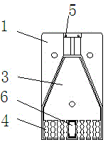
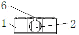
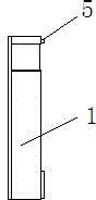
[0018] Such as figure 1 A ribbon-shaped optical cable stripping protector shown in —5 includes a bottom box 1 and a cover plate 7 installed on the bottom box 1, and the bottom box 1 is provided with a cable inlet 2, a wire feeding groove 3 and a fiber splitting The fiber outlet vertical slot 4, the cable inlet hole 2 communicates with the wire feeding slot 3, and the wire feeding slot 3 communicates with the fiber splitting and fiber output vertical slot 4; the bottom box 1 is equipped with a positioning pin 5 and a snap ring frame 6. The bottom box 1, the cable inlet hole 2, the wire feeding groove 3, the fiber splitting fiber outlet vertical groove 4, the positioning pin 5 and the snap ring frame 6 are injection molded at one time; the bottom box 1 passes through the positioning pin 5, the snap ring The frame 6 is connected with the cover plate 7; the cover plate 7 is equipped with a buckle 8, and the cover plate 7 is provided with a positioning hole 9, the snap ring frame 6...


PUM


Abstract

The invention discloses an optical fiber ribbon cable stripping protector. The optical fiber ribbon cable stripping protector comprises a base box, a cable inlet hole, a wire feeding groove and fiber separating and outgoing vertical grooves are formed in the base box, the cable inlet hole is communicated with the wire feeding groove, the wire feeding groove is communicated with the fiber separating and outgoing vertical grooves, a positioning pin and a snap ring rack are mounted on the base box, and the base box is connected with a cover plate through the positioning pin and the snap ring rack. The optical fiber ribbon cable stripping protector has the advantages of simple structure, convenient operation and low costs.

Description

technical field [0001] The invention relates to the technical field of communication equipment, in particular to a ribbon optical cable stripping protector. Background technique [0002] When introducing outdoor ribbon optical cables into optical distribution equipment such as optical fiber distribution frames and optical cable transfer boxes, the optical cables need to be fixed, stripped, split for protection, and the metal reinforcing core is grounded. The ribbon optical cables used in the prior art are stripped The protector and the fiber splitting protection device use layered pressing plates processed by metal materials, which have the following disadvantages: [0003] 1. After sheet metal processing, surface treatment is required, which is cumbersome and costly; [0004] 2. When the fiber optic cable is divided, the pressure plate must be superimposed layer by layer, which is inconvenient to operate. Contents of the invention [0005] The object of the present inve...

Claims


Application Information

Patent Timeline
IPC IPC(8): G02B6/44
Inventor 郭飞王英浩王吉
Owner ZHEJIANG RONGHUI COMM EQUIP
Why Eureka
Try Eureka