Liquid Crystal Panel Detection Device

A liquid crystal panel and inspection device technology, applied in the direction of measuring devices, optics, instruments, etc., can solve the problems of insufficient reach and insufficient light irradiation of the liquid crystal panel 1, achieve compact device structure, shorten production cycle time, and shorten production cycle time the effect of time

Active Publication Date: 2014-10-15
NIHON MICRONICS
View PDF9 Cites 11 Cited by
  • Summary
  • Abstract
  • Description
  • Claims
  • Application Information

AI Technical Summary

Benefits of technology

This technology allows for quicker and more efficient detection of defects during manufacturing processes by performing multiple tests at different stages simultaneously or sequentially while also allowing for precise positional control over each test area. By utilizing an optically transparent plate called polarization film that absorbs certain wavelengths of visible light when exposed to ultraviolet rays (UV), this technique makes it possible to inspect both dark areas and clear surfaces accurately even after they have been covered up by other layers such as paint coatings or plating films. Additionally, there are several technical features associated with these techniques:

Problems solved by technology

This technical problem addressed in these prior art techniques relating to inspecting display panels involves the use of multiple lights sources and cameras to capture images while avoiding interference issues associated with ambient light conditions. Additionally, the current method requires separate mountings for both the light source and camera components, leading to bulky size and increased costs.

Method used


Image

  • Liquid Crystal Panel Detection Device
  • Liquid Crystal Panel Detection Device
  • Liquid Crystal Panel Detection Device

Examples


Embodiment Construction

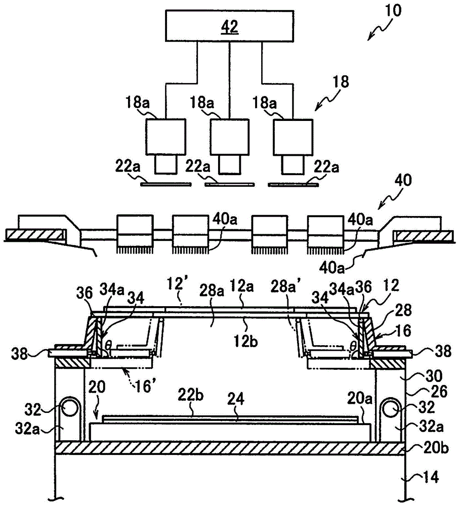
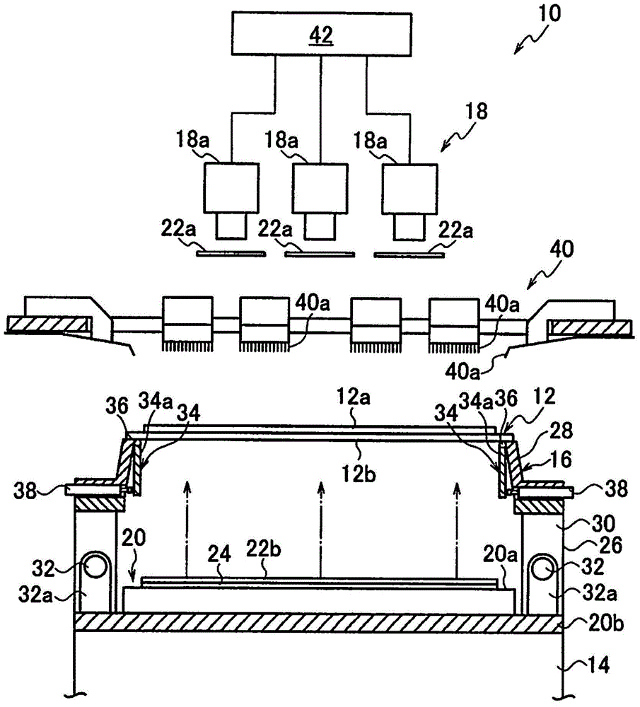
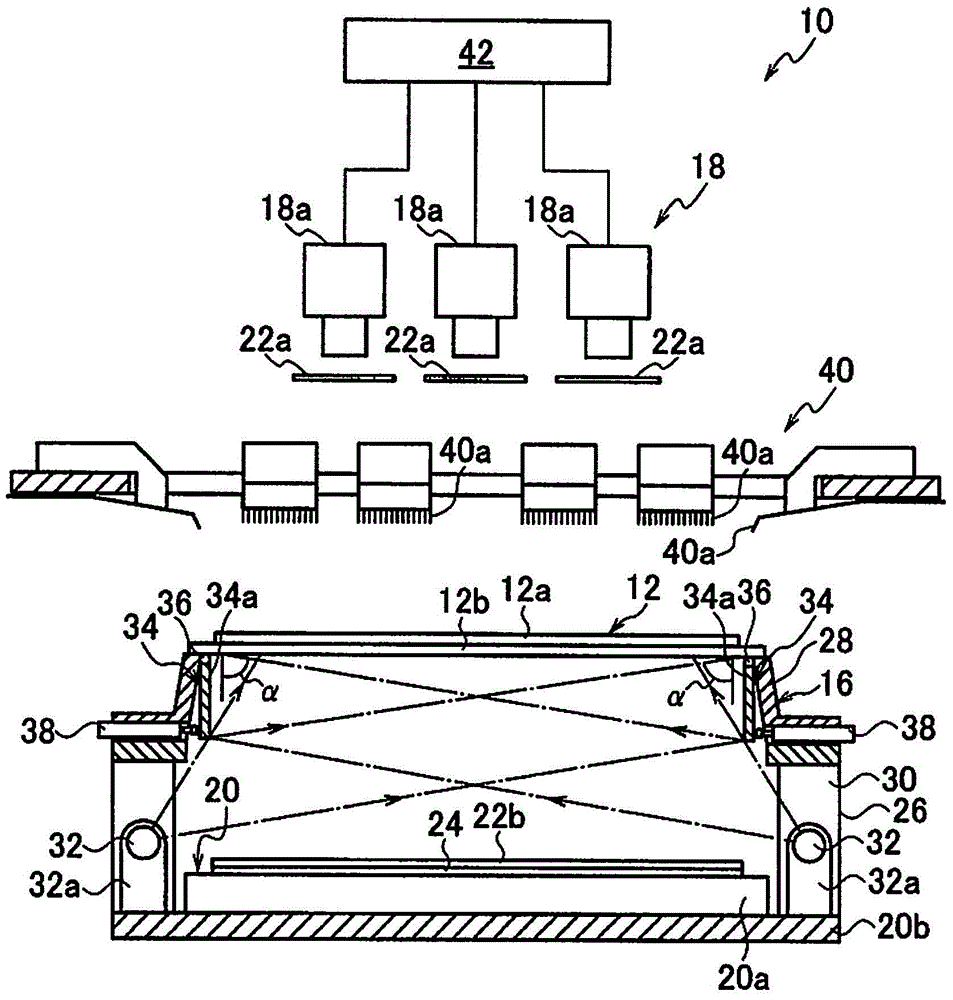
[0036] The liquid crystal panel inspection apparatus 10 of this invention is applied to the inspection of the liquid crystal panel 12 which does not have a pair of polarizing plates. The liquid crystal panel 12 has a rectangular planar shape, and conventionally known electrodes (not shown) for applying a driving voltage to each pixel of the liquid crystal panel 12 are arranged on each side of one surface (upper surface) 12 a of the liquid crystal panel 12 .

[0037] The liquid crystal panel inspection device 10 includes: a lifting table 14, which can be figure 1 The vertical direction (z-axis direction) is raised and lowered in the middle view; the worktable 16 is supported on the lifting platform and is used to hold the liquid crystal panel 12 as the object to be inspected; and the imaging unit 18 is able to An imaging means such as a CCD camera captures images of the upper surface 12 a of the liquid crystal panel 12 held on the table from above the table 16 .

[0038] The ...


PUM


Abstract

The present invention provides a compact liquid crystal panel detection device which can determine a defect address rapidly and accurately. The detection device comprises a first polarizing film and a second polarizing film which are arranged at the upper and lower parts of a liquid crystal panel on a workbench respectively; a backlight unit which irradiates the liquid crystal panel at a right angle with the lower surface, from the lower surface of the liquid crystal panel on the workbench, and via the second polarizing film; an inclined illumination light source which irradiates the liquid crystal panel on the workbench aslant from the lower part of the lower surface; a probe unit for applying voltages on the pixels of the liquid crystal panel on the workbench to detect the bright spots of the liquid crystal panel; a camera head for shooting the upper surface of the liquid crystal panel under the state of selectively receiving any one of the irradiation light coming from the backlight unit and the inclined irradiation light coming from the inclined illumination light source, and via the first polarizing film; and a reflecting part for guiding the inclined illumination light to the lower surface of the liquid crystal panel in a manner that the inclined illumination light is irradiated to the liquid crystal panel at an appropriate incident angle.

Description


Claims


Application Information

Patent Timeline
Owner NIHON MICRONICS
Why Eureka
Try Eureka