Compression resin packaging method and compression resin packaging device for electronic components

A technology for electronic component installation and electronic components, which is applied in the direction of electrical components, electric solid devices, circuits, etc., and can solve problems such as inability to form packages with thickness

Active Publication Date: 2014-10-15
TOWA
View PDF5 Cites 10 Cited by
  • Summary
  • Abstract
  • Description
  • Claims
  • Application Information

AI Technical Summary

Problems solved by technology

[0013] Inability to mold the thickness of the package to a specified uniform thickness

Method used


Image

  • Compression resin packaging method and compression resin packaging device for electronic components
  • Compression resin packaging method and compression resin packaging device for electronic components
  • Compression resin packaging method and compression resin packaging device for electronic components

Examples


no. 1 approach )

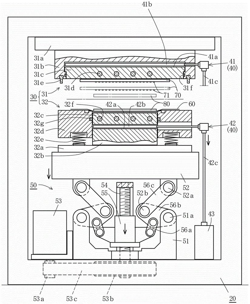
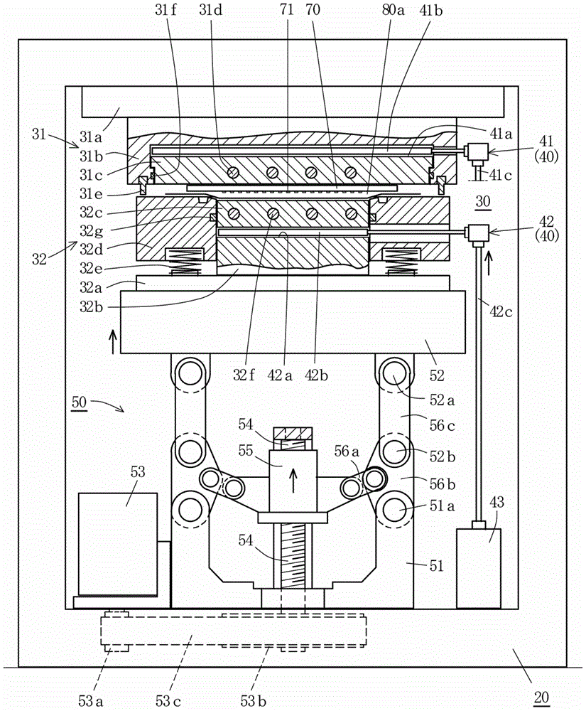
[0086] Figure 1 to Figure 5 is the first embodiment of the present invention, figure 1 and figure 2 shows the overall structure of the compressed resin encapsulation device, and, in addition, Figure 3 to Figure 5 Indicates its main part.

[0087] In addition, this compression resin packaging device shows a structure in which each component is held by a press frame (holder). That is, an upper die 31 for compression molding is disposed on the lower surface side of the upper end portion of the frame-shaped press frame 20, and a die opening and closing mechanism 50, which will be described later, is disposed below the upper die 31 so that it can move up and down. A lower mold 32 for compression molding is provided. The upper mold 31 and the lower mold 32 constitute a mold 30 for compression molding.

[0088] In addition, the upper mold 31 includes: an upper mold base 31a fixedly installed on the lower surface side of the upper end of the pressing frame 20; an upper mold h...

no. 2 approach )

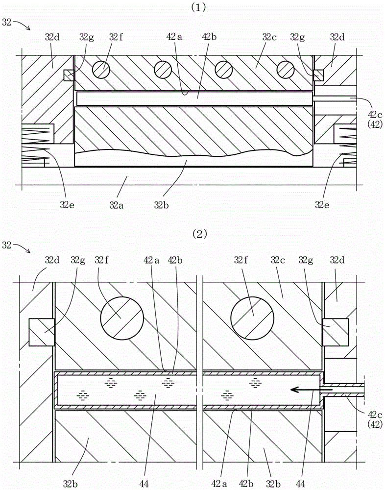
[0110] Below, based on Figure 6 A second embodiment of the present invention will be described.

[0111] Figure 6 is a compression resin sealing device showing a second embodiment of the present invention, Figure 6 (1) indicates the main part of the resin molding part when the upper and lower molds are opened. In addition, Figure 6 (2) indicates the main part of the resin molded part when the upper and lower molds are clamped. The second embodiment differs from the first embodiment in the following points. In addition, other points are substantially the same as those of the first embodiment. Therefore, different points will be described, and the same reference numerals will be used for substantially the same components as those of the first embodiment, and duplication of description will be avoided.

[0112] That is, if Figure 6 As shown in (2), a narrow gap 34c for allowing the remaining resin 80b to flow out of the lower mold cavity 34a is provided between the mol...

no. 3 approach )

[0118] Figure 7 is a compression resin sealing device showing a third embodiment of the present invention, Figure 7 (1) indicates the main part of the resin molding part when the upper and lower molds are opened. In addition, Figure 7 (2) indicates the main part of the resin molded part when the upper and lower molds are clamped. The third embodiment differs from the first and second embodiments in the following points. In addition, other points are substantially the same as those of the first and second embodiments. Therefore, different points will be described, and the same reference numerals will be used for components that are substantially the same as those in the first and second embodiments, and duplication of description will be avoided.

[0119] That is, if Figure 7 As shown, the lower mold 32 has a cavity bottom surface (cavity bottom surface member 32c of the first and second embodiments) and a cavity side surface (cavity side surface member 32d of the first...


PUM


Abstract

The present invention relates to a compression resin packaging method and a compression resin packaging device for electronic components. The present invention simplifies the compression resin packaging device which integrally packages the electronic components on a large-scale substrate and resin in a package, and raises precision (deviation) of thickness of the package. Sheet-like resin having a shape-preserving property carried on a release liner is supplied into a lower mold cavity, mold assembling is performed for upper and lower molds, residual resin in the lower mold cavity is leaded into a residual resin containing part at the outside world through a gap between the upper mold and the lower mold, so that in a resin packaging step, a gap between a bottom surface of the lower mold cavity at a final position of the mold assembling of the upper and lower molds and an electronic component installing surface in the large-scale substrate is set to be equal to the gap of the package thickness for performing resin packaging for the electronic components of the large-scale substrate, by further compressing the fused resin material in the lower mold cavity under the conditions of low speed and low pressure, the electronic components on the large-scale substrate are packaged integrally with the resin.

Description

technical field [0001] The present invention relates to a so-called resin encapsulation method and an improvement of a resin encapsulation device in which a plurality of electronic components (semiconductor chips) mounted on a large substrate are encapsulated and molded (resin injection molding) using a resin by a compression molding method. Background technique [0002] As a method of resin-packaging electronic components on a large substrate, a compression molding method is known. Such as Figure 8 As schematically shown in , the device for performing the compression molding method at least has a compression molding mold composed of an upper mold 1 and a lower mold 2, and is arranged so that the upper and lower molds 1, 2 pass through an appropriate mold opening and closing mechanism (not shown) icon) relatively engages and disengages. Furthermore, in order to resin-seal the electronic components 4 on the large board|substrate 3 using this resin sealing apparatus, it carr...

Claims


Application Information

Patent Timeline
Patent Type & Authority Applications(China)
IPC IPC(8): H01L21/56B29C45/14
CPCH01L2224/73265H01L2224/48227H01L2224/32225H01L21/565H01L24/73H01L21/56B29C45/14008
Inventor 高濑慎二川本佳久砂田卫
Owner TOWA
Why Eureka
Try Eureka