Electric driver for motor vehicle

A technology for electric drives and motor vehicles, applied in the direction of electromechanical devices, electrical components, electric components, etc., can solve problems such as unfavorable and high installation costs, and achieve the effect of improving interference removal, spark interference removal, and interference removal degree

Active Publication Date: 2014-10-15
ROBERT BOSCH GMBH
View PDF5 Cites 1 Cited by
  • Summary
  • Abstract
  • Description
  • Claims
  • Application Information

AI Technical Summary

Problems solved by technology

Here, the high installation costs have proven to be a disadvantage in princip

Method used


Image

  • Electric driver for motor vehicle
  • Electric driver for motor vehicle
  • Electric driver for motor vehicle

Examples


Embodiment Construction

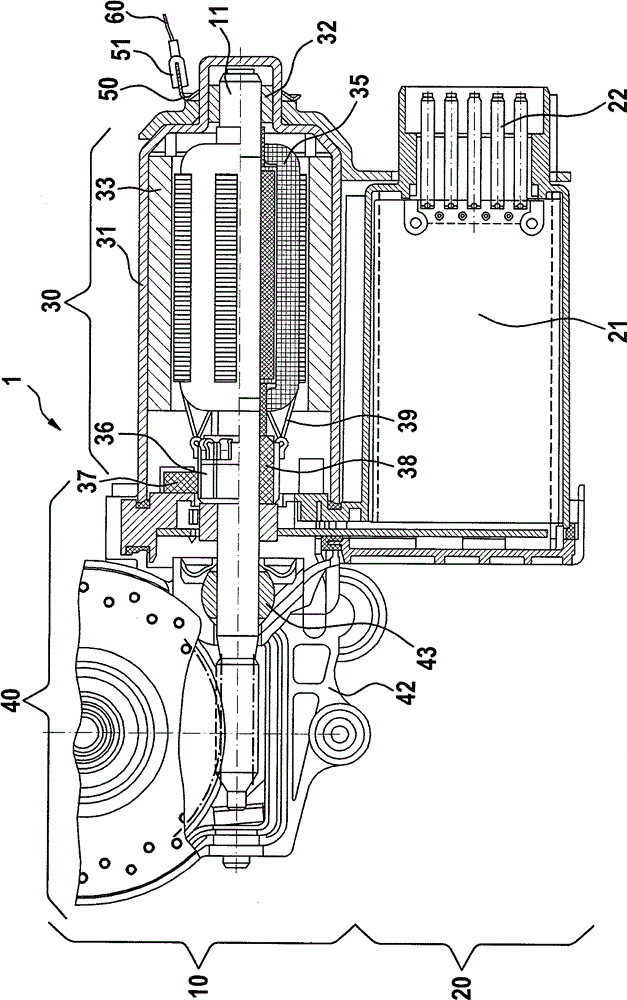
[0022] figure 1 A longitudinal section through an electric drive 1 according to the invention is shown with a drive module 10 and an electronics module 20 , the drive module 10 comprising a motor module 30 and a transmission module 40 . In this case, the motor module 30 is shown in section in the upper part and in a cutaway view in the lower part. Brushes 37 and commutator laminations 38 can be seen in the upper cutaway. Furthermore, the motor module 30 includes an armature 35 which is connected to the direct current grid via a commutator 36 . The commutator 36 is connected to the armature 35 via a connecting hook 39 . Since the corresponding winding inductance is short-circuited via the winding resistance and the brush transition resistance when the brush 37 moves from one segment 38 to the next, a commutation occurs during operation of the motor module 30 at each commutation. spark discharge. Such sparkovers on the one hand shorten the service life of the motor module 10...


PUM


Abstract

The invention relates to an electrical driver (1) for a motor vehicle, which comprises a driving module (10) with a motor module (30), and an electronic module (20). An interference device for the motor module (30) is arranged between the driving module (10) and the electronic module (20). The motor module (30) is provided with an electrode cover (31) used for accommodating a motor. The electrode cover (31) is connected with the motor module (30) through at least one fixing element (50). The fixing element (50) is provided with an additional contact element (51) used for connecting the electrode cover (31) with the bond strap of a vehicle.

Description

technical field [0001] The invention relates to an electric drive, in particular an electric adjustment drive in a motor vehicle, wherein an adjustment drive also refers to a sliding sunroof drive, a door drive, a tailgate drive, a seat adjustment drive or a window lift drive . Background technique [0002] Such an electric drive is used, for example, in a vehicle as a DC motor for the auxiliary drive and / or the convenience drive and generally includes a drive module and an electronics module, which in turn can consist of a motor module and a transmission module. The drive module usually consists of an electric motor whose armature (rotor) mounted on the motor shaft is rotatably mounted in a metal pole shield (Poltopf), in which the permanent magnets are held in a two-pole or multipole arrangement . In this case, the pole shield or the housing is usually mounted via roller bearings on the center or end of the armature shaft and fastened by means of fastening elements. The...

Claims


Application Information

Patent Timeline
IPC IPC(8): H02K11/02H02K5/22
CPCH02K5/1672H02K7/081H02K7/1166H02K5/22H02K11/0089H02K7/116H02K11/00H02K11/40
Inventor F.塔施V.赫特维克T.胡克
Owner ROBERT BOSCH GMBH
Why Eureka
Try Eureka