
Method and device for processing uplink and downlink resource configuration information

A technology of resource configuration information and information processing methods, applied in the field of communication, can solve the problems of high equipment implementation complexity, large signaling overhead, and large delay, and achieve the goals of increasing control signaling overhead, efficient and accurate transmission, and increasing complexity Effect

Active Publication Date: 2014-10-15
ZTE CORP
View PDF6 Cites 33 Cited by
  • Summary
  • Abstract
  • Description
  • Claims
  • Application Information

AI Technical Summary

Problems solved by technology

[0015] The present invention provides a method and device for processing uplink and downlink resource configuration information, so as to at least solve the problem of long cycle and large delay when implementing high-level signaling in the context of dynamically adjusting uplink and downlink configurations in the related art, and There is a problem of inconsistency in the implementation of signaling between the terminal and the base station, and when the physical layer signaling is used to implement, there are problems of high physical layer control signaling overhead and high complexity of equipment implementation

Method used


Image

  • Method and device for processing uplink and downlink resource configuration information
  • Method and device for processing uplink and downlink resource configuration information
  • Method and device for processing uplink and downlink resource configuration information

Examples


Embodiment 1

[0095] Figure 11 It is a schematic diagram of a preferred embodiment 1 according to an embodiment of the present invention, such as Figure 11 As shown, in a wireless frame, subframes 0 and 5 are fixed downlink subframes; subframes 2 and 7 are fixed uplink subframes; subframes 1 and 6 are special subframes, including DwPTS, GT, and UpPTS; Frames 3, 4, 8, and 9 are flexible subframes.

[0096] When subframe 4 of radio frame A transmits downlink signals, the uplink and downlink configuration signaling of the next radio frame is transmitted on subframe 4, that is, configuration 2 in Table 1.

Embodiment 2

[0098] Figure 12 is a schematic diagram of a preferred embodiment 2 according to an embodiment of the present invention, so Figure 12 As shown, in a wireless frame, subframes 0 and 5 are fixed downlink subframes; subframes 2 and 7 are fixed uplink subframes; subframes 1 and 6 are special subframes, including DwPTS, GT, and UpPTS; Frames 3, 4, 8, and 9 are flexible subframes.

[0099] When subframe 8 of radio frame A transmits a downlink signal, the uplink and downlink transmission directions of the flexible subframe in the next radio frame transmitted on subframe 8 are: UDDD. Among them, the possible combinations of transmission directions of flexible subframes 3, 4, 8, and 9 are UUUU; UUUD; UDDD; DDDD.

Embodiment 3

[0101] Figure 13 is a schematic diagram of the third preferred embodiment according to the embodiment of the present invention, so Figure 13 As shown, in a wireless frame, subframes 0 and 5 are fixed downlink subframes; subframe 2 may be fixed uplink subframes; subframes 1 and 6 are special subframes, including DwPTS, GT, and UpPTS; subframe 3 , 4, 7, 8, and 9 are flexible subframes.

[0102] When subframe 8 of radio frame A transmits a downlink signal, the uplink and downlink transmission directions of the flexible subframe in the next radio frame transmitted on subframe 8 are: UUDDD. Among them, the possible combinations of transmission directions of flexible subframes 3, 4, 7, 8, and 9 are UUUUU; UUUUD; UUUDD; UUDDD; UDDDD; DDDDD.


PUM


Abstract

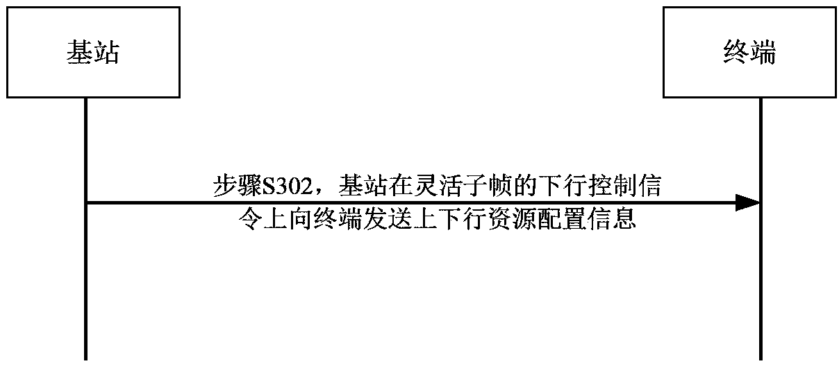
The invention provides a method and a device for processing uplink and downlink resource configuration information. The method comprises a step of transmitting uplink and downlink resource configuration information on a downlink control signaling of a flexible subframe. The invention solves the problems that in a condition that the uplink and downlink configuration is dynamically adjusted in the related technology, when the high level signal realization is adopted, the cycle and the delay are long , and the execution for the signaling between the terminal and the base station is not constant, and that when the physic layer signaling realization is adopted, the cost for the physic layer control signaling is big and the complexity for the device realization is high. The invention can effectively avoid the problems that the high level signaling delay is long and that the understanding for the execution timing of the terminal and the base station inconsistent on the premises that the extra physic layer resources are not occupied, the extra cost for the control signaling is not added and the complexity of the device is not increased, and can realize the highly efficient and precise transmission of the uplink and downlink resource configuration information.

Description

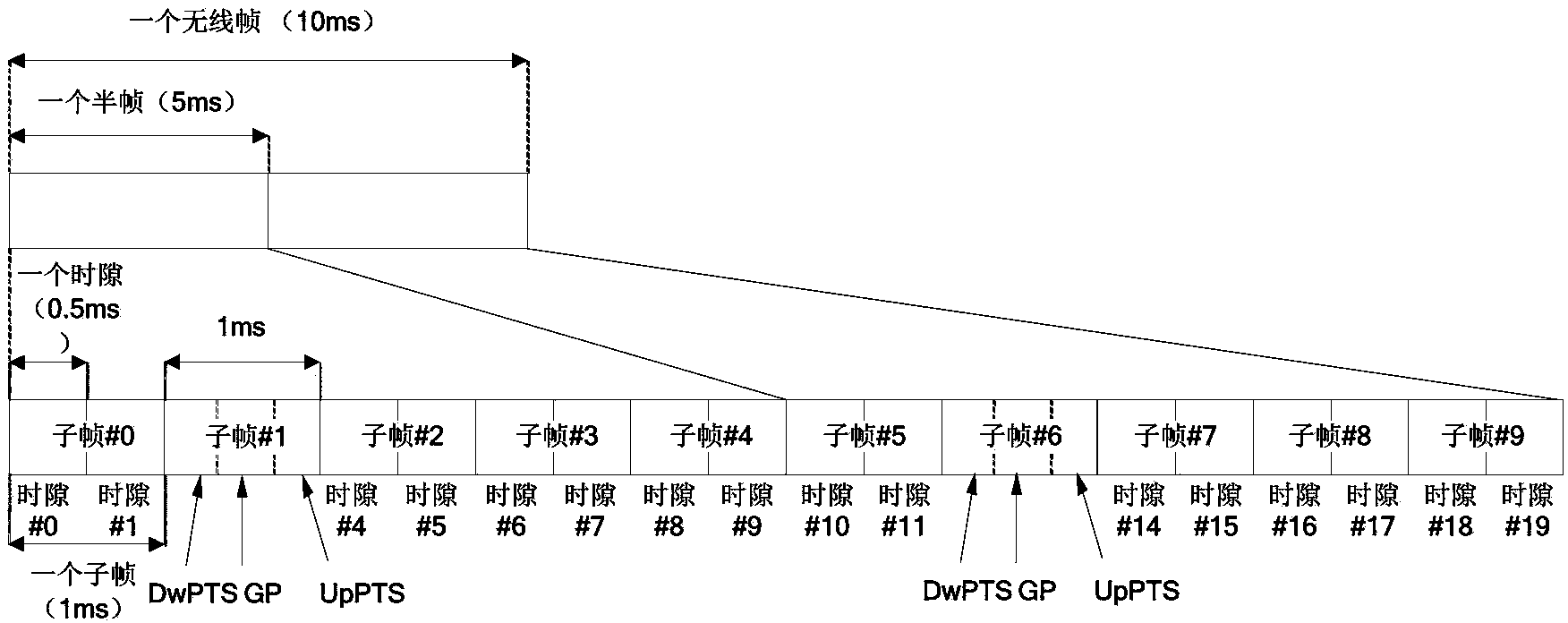
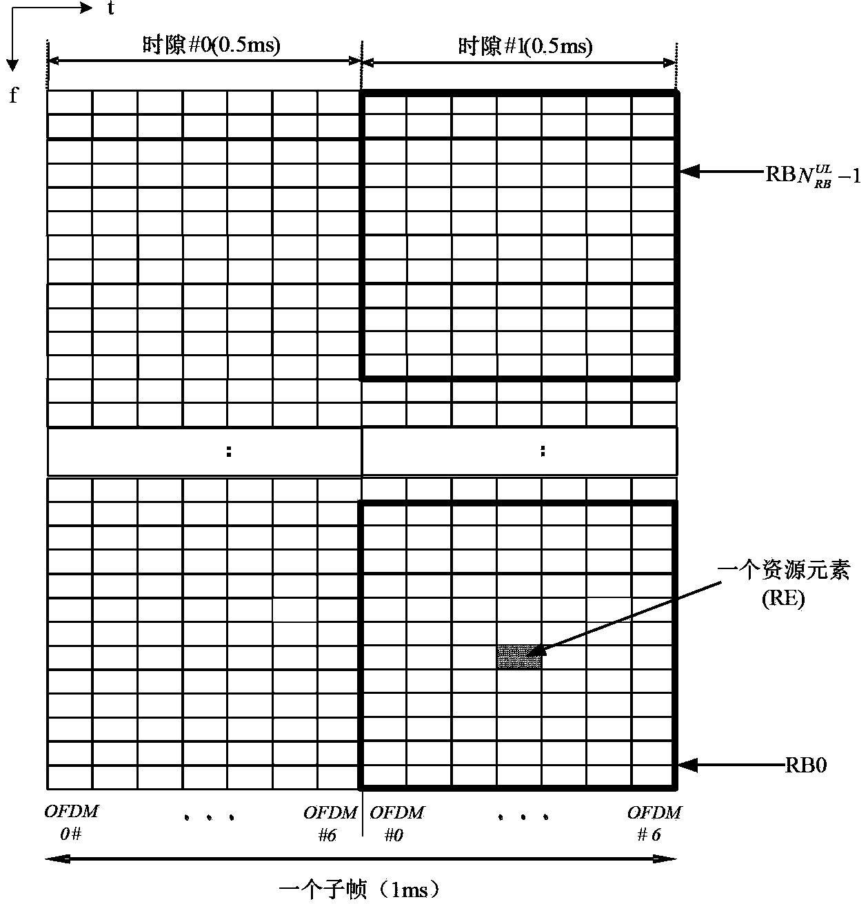
technical field [0001] The present invention relates to the communication field, in particular, to a method and device for processing uplink and downlink resource configuration information. Background technique [0002] The Time Division Duplex (TDD for short) system divides uplink (sent by the terminal to the base station) and downlink (sent by the base station to the terminal) resources in the time domain, and usually performs uplink and downlink in units of time slots or subframes. Allocation of resources. Generally, the base station notifies all terminals in the cell of the allocation of uplink and downlink resources by broadcast signaling in a semi-static manner. [0003] figure 1 It is a schematic diagram of the frame structure of the TDD mode of the Long Term Evolution (LTE) system in related technologies, as shown in figure 1 As shown, the frame structure is also called the second type of frame structure (ie, frame structure type2). In this frame structure, a wir...

Claims


Application Information

Patent Timeline
Patent Type & Authority Applications(China)
IPC IPC(8): H04W72/04H04L5/00
Inventor 郝鹏李卫敏任璐
Owner ZTE CORP
Learn More