
Linear glue-dripping head and method for dripping glue on lamp ring of lamp by linear glue-dripping head

A glue dispensing and line type technology, applied in the field of glue dispensing head, can solve the problems of difficult glue dispensing, low glue dispensing efficiency, high labor intensity, etc., and achieve the effect of improving glue dispensing efficiency, shortening glue dispensing time, and reducing labor intensity

Active Publication Date: 2014-10-22
OCEANKING DONGGUAN LIGHTING TECH +2
View PDF4 Cites 1 Cited by
  • Summary
  • Abstract
  • Description
  • Claims
  • Application Information

AI Technical Summary

Problems solved by technology

In this way, it is easy to drop the glue to the parts that do not need glue, resulting in a waste of glue cleaning time, and this glue dropping method requires high personnel skills
Unskilled glue dispensing stations can easily drop glue to the parts that do not need glue, resulting in large area of ​​glue clearing, and the speed of glue dispensing bit by bit is also slow, which is a waste of time
For example, when using a syringe to dispense glue, it is necessary to drip a circle of glue in the gap of a circular lamp circle. The glue dispensing efficiency is low, and the glue dispensing requires skilled labor, otherwise it is easy to drip a lot of glue on the transparent parts of the lamp. , resulting in difficulty in clearing the glue, such a little bit of glue, the labor intensity is relatively large

Method used


Image

  • Linear glue-dripping head and method for dripping glue on lamp ring of lamp by linear glue-dripping head
  • Linear glue-dripping head and method for dripping glue on lamp ring of lamp by linear glue-dripping head
  • Linear glue-dripping head and method for dripping glue on lamp ring of lamp by linear glue-dripping head

Examples


Embodiment Construction

[0036] In order to facilitate the understanding of the present invention, the present invention will be described more fully below with reference to the associated drawings. Preferred embodiments of the invention are shown in the accompanying drawings. However, the present invention can be embodied in many different forms and is not limited to the embodiments described herein. On the contrary, these embodiments are provided to make the understanding of the disclosure of the present invention more thorough and comprehensive.

[0037] It should be noted that when an element is referred to as being “fixed” to another element, it can be directly on the other element or there can also be an intervening element. When an element is referred to as being "connected to" another element, it can be directly connected to the other element or intervening elements may also be present. The terms "vertical," "horizontal," "left," "right," and similar expressions are used herein for purposes ...


PUM


Abstract

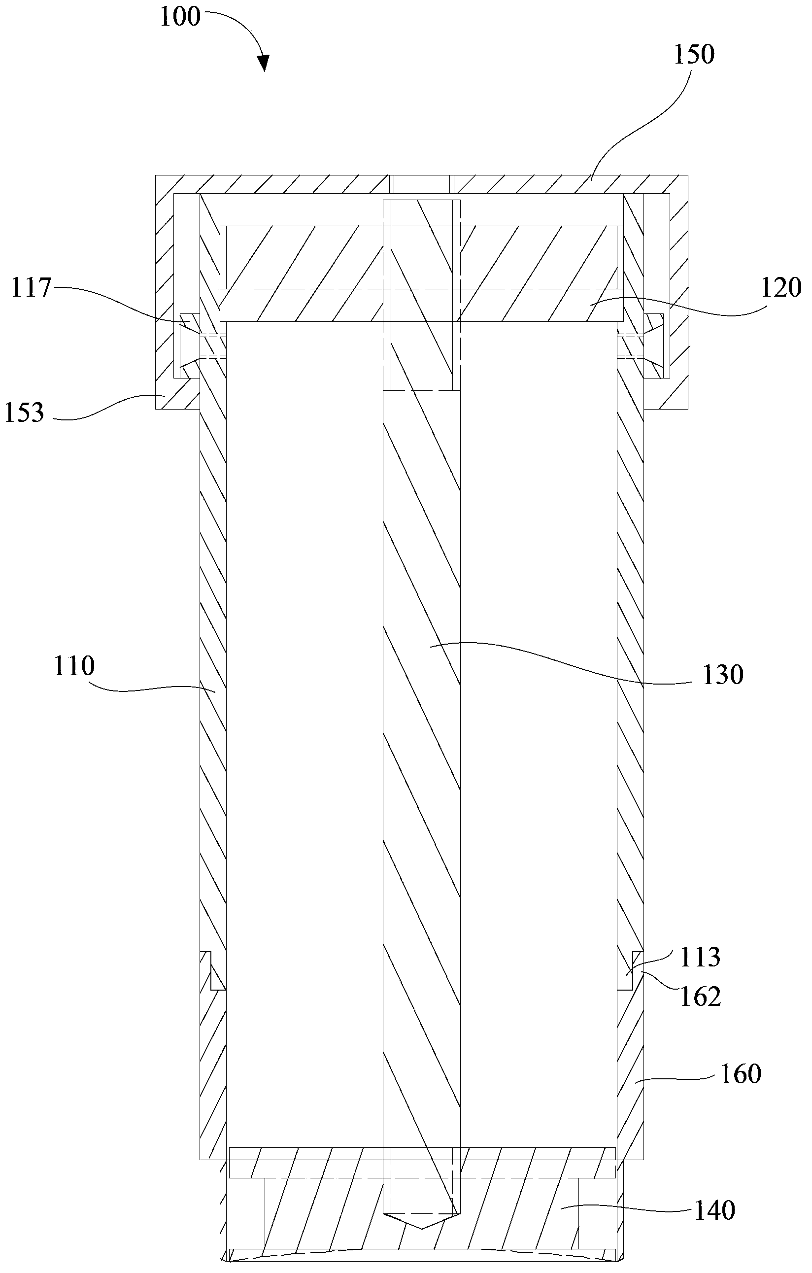
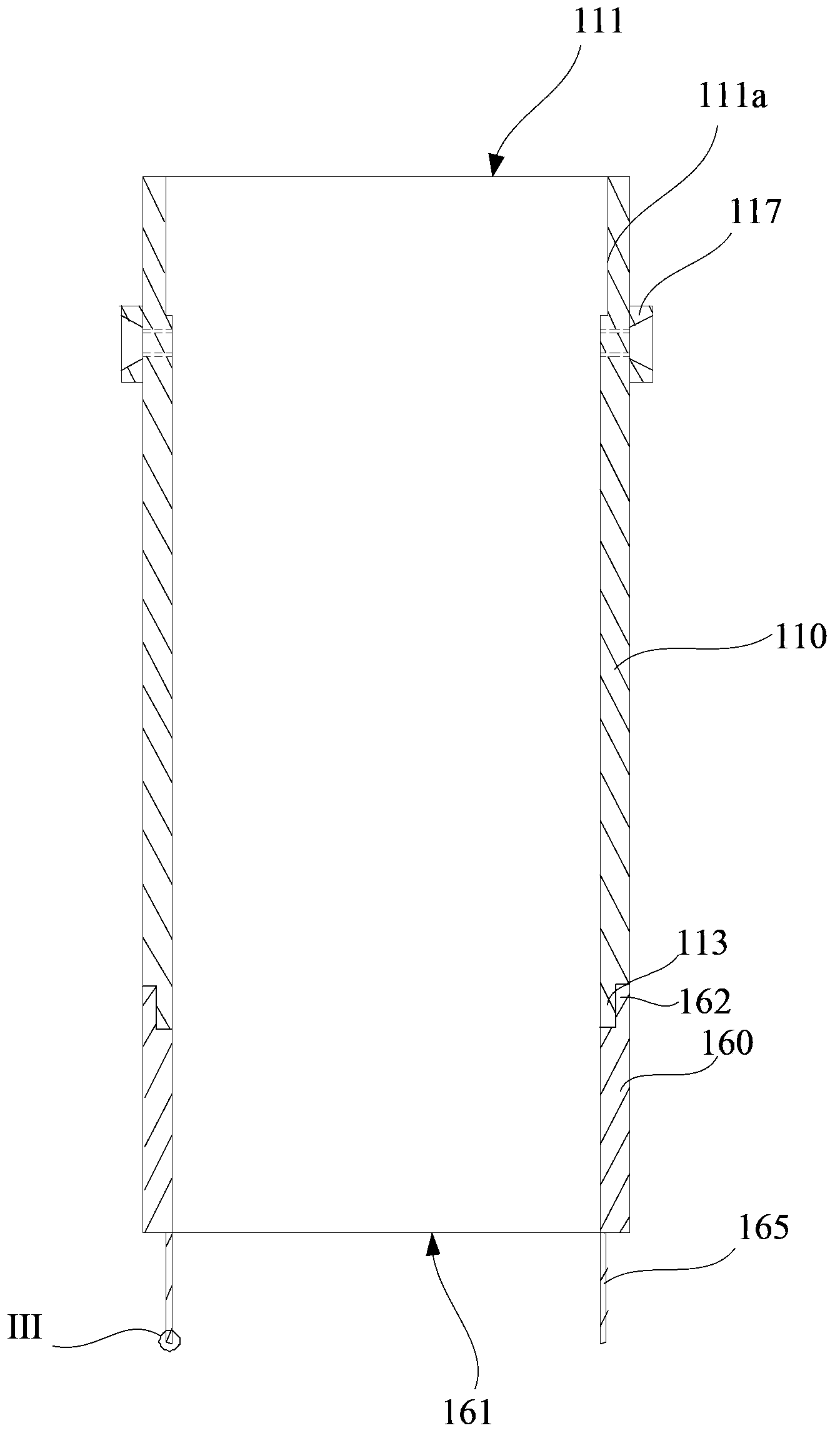
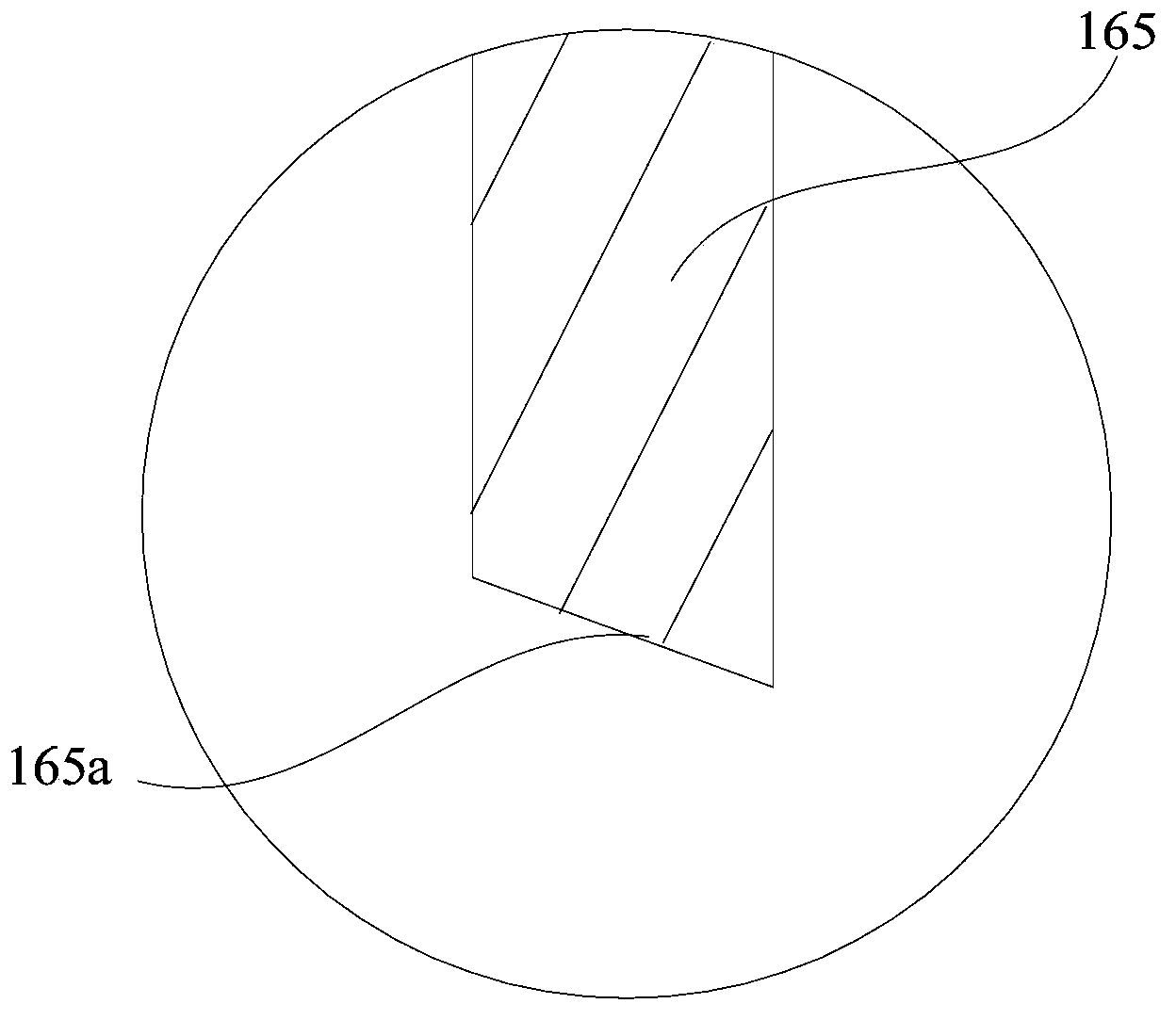
The invention discloses a linear glue-dripping head. The linear glue-dripping head comprises a glue storage cylinder which has a cylindrical structure having both open ends and is provided with an inflation opening and a connection opening, a glue outlet part which has a cylindrical structure having both open ends and has one open end detachably connected to the connection opening of the glue storage cylinder and the other open end as a glue-dripping opening, a glue amount control ring which is arranged the end surface of the glue-dripping opening, a fixing disc which is detachably fixed in the glue storage cylinder, a support rod of which one end is connected to the fixing disc, a glue amount control disc which is connected to one end of the support rod far away from the fixing disc and has preset gaps between the periphery and the inner wall of the glue amount control disc so that glue-dripping mouths are formed between the glue amount control disc and the glue amount control ring, and a sealing cover which is detachably fixed to the inflation opening. The linear glue-dripping head can produce drops having various shapes by one step, shortens glue-dripping time, improves glue-dripping efficiency and glue-dripping quality, and reduces glue-dripping labor intensity, glue-dripping difficulty and a production cost. The invention also provides a method for dripping glue on a lamp ring of a lamp by the linear glue-dripping head.

Description

【Technical field】 [0001] The invention relates to a glue dispensing head, in particular to a linear glue dispensing head and a glue dispensing method for a lamp ring of a lamp using the linear glue dispensing head. 【Background technique】 [0002] Now glue dispensing, no matter it is automatic, semi-automatic or manual glue dispensing equipment, all use syringes to dispense glue bit by bit into various shapes of lines. In this way, the glue is easy to drop the glue to the parts that do not need glue, resulting in a waste of glue cleaning time, and this glue dropping method requires high personnel skills. Unskilled glue dispensing stations can easily drop glue to parts that do not need glue, resulting in a large area of ​​glue clearing, and the speed of glue dispensing is slow, which is a waste of time. For example, when using a syringe to dispense glue, it is necessary to drip a circle of glue in the gap of a circular lamp circle. The glue dispensing efficiency is low, and t...

Claims


Application Information

Patent Timeline
IPC IPC(8): B05C5/00B05C11/10B05D1/26
Inventor 周明杰习文勇
Owner OCEANKING DONGGUAN LIGHTING TECH
Learn More