Continuous corundum smelting flow furnace

A technology of corundum and discharge port, which is applied in the field of corundum smelting furnaces, can solve the problems of high temperature waste heat loss, high heat utilization efficiency, power grid impact, etc., and achieve the effects of convenient centralized smoke and dust removal, low production site requirements, and high electric heating efficiency

Active Publication Date: 2015-09-30
SIPPR ENG GROUP
View PDF7 Cites 0 Cited by
  • Summary
  • Abstract
  • Description
  • Claims
  • Application Information

AI Technical Summary

Problems solved by technology

Fixed furnace frit method. The furnace body of the electric furnace is placed on the furnace car. After the smelting is completed, it is transported to the cooling field. After cooling, it is pulled to the furnace out of the furnace. After the frit is taken out, it is transferred to the furnace repairing field for repair, and then transferred to the furnace location It will be produced in the next cycle, so there are problems such as low heat utilization rate, too much material for returning to the furnace, and high labor intensity.
The dumping furnace smelting method is an improvement on the basis of the fixed furnace frit method. The smelting cycle is shorter than the fixed furnace frit method, and there are more corundum crystal aggregates, and the heat utilization efficiency is higher. Its shortcomings are: 1. With the smelting Different stages have different smelting power, and high-power conversion will easily cause a certain impact on the power grid; 2. After the smelting is completed, when the furnace body rotates and pours high-temperature melt into the receiving bag, due to the high pouring height, The corundum melt at 2050°C pours down from a height of more than 5 meters, and the rapid cooling of the melt has a great impact on the crystallization and homogenization of corundum, which reduces the quality of smelted products; 3. The deposition of ferrosilicon during the smelting process is easy to cause 4. Since the furnace body requires a large rotating space, the space reserved around the furnace body is relatively large, resulting in a large dust removal air volume and high energy consumption. When the furnace body is rotated, the drop pipe The height difference from the blanking point is large, resulting in more dust and higher material consumption
[0003] At the same time, the above two smelting methods are batch smelting, and the high-temperature waste heat in the furnace is lost in the process of shutdown and conversion, resulting in a large amount of energy waste

Method used


Image

  • Continuous corundum smelting flow furnace
  • Continuous corundum smelting flow furnace

Examples


Embodiment Construction

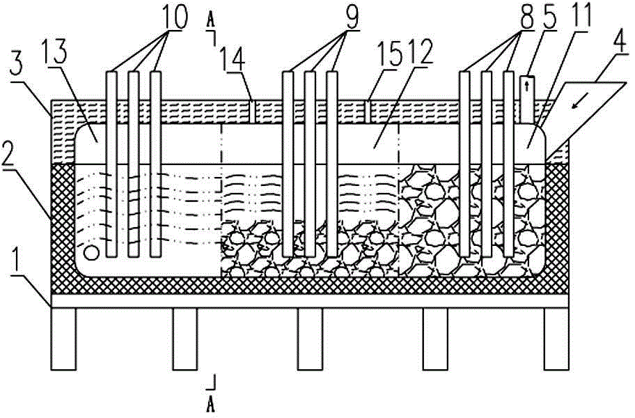
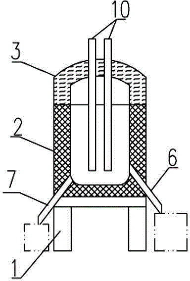
[0011] Such as figure 1 , 2 As shown, the continuous corundum smelting exile furnace according to the present invention includes an upper opening furnace body 2 arranged on a support platform 1, a furnace cover 3 which is sealed and buckled on the upper opening furnace body 2, and is arranged in a furnace cavity The heating electrode inside and the feed port 4, discharge port and smoke exhaust port 5 communicated with the furnace cavity; the feed port 4 is arranged on the right side wall of the furnace cover 3, and the discharge ports are respectively The corundum melt discharge port and the ferrosilicon melt discharge port provided on the opposite side walls of the left end of the furnace body 2, the height of the corundum melt discharge port is greater than the height of the ferrosilicon melt discharge port, and the corundum melt The liquid flow outlet and the ferrosilicon melt outlet are respectively provided with guide pipes 6 and 7 obliquely downward; the smoke exhaust p...


PUM


Abstract

The invention discloses a continuous type drainage furnace for corundum smelting. The continuous type drainage furnace comprises an upper-opening furnace body arranged on a supporting platform, a furnace lid buckled to the upper-opening furnace body in a sealing mode, three sets of heating electrodes arranged in a furnace chamber, a charging hole, discharging holes and a smoke exhaust hole, wherein the charging hole, the discharging holes and the smoke exhaust hole are communicated with the furnace chamber. The discharging holes comprise the corundum solution drainage hole and the silicon iron solution drainage hole, wherein the corundum solution drainage hole and the silicon iron solution drainage hole are formed in the two opposite side walls of the left end of the furnace body respectively. The heating electrodes arranged in the furnace chamber from right to left at intervals divide the furnace chamber into a smelting area, a refining area and a discharging area. The left sides and the right sides of the heating electrodes, located in the refining area, on the top wall of the furnace lid are provided with sampling holes respectively. The continuous type drainage furnace has the advantages of achieving continuous production of corundum smelting, has low requirements for production fields and is easy and convenient to operate. Due to the heating electrodes arranged in the furnace chamber from right to left at intervals, the electric heating efficiency is high. The discharging area is provided with the corundum solution drainage hole and the silicon iron solution drainage hole, and therefore corundum solutions and silicon iron solutions can be separately discharged.

Description

technical field [0001] The invention relates to a corundum smelting furnace, in particular to a continuous corundum smelting exile furnace. Background technique [0002] At present, the corundum smelting methods are mostly fixed furnace frit method and dumping furnace smelting method. Fixed furnace frit method. The furnace body of the electric furnace is placed on the furnace car. After the smelting is completed, it is transported to the cooling field. After cooling, it is pulled to the furnace out of the furnace. After the frit is taken out, it is transferred to the furnace repairing field for repair, and then transferred to the furnace location It will be produced in the next cycle, so it has the disadvantages of low heat utilization rate, too much material for returning to the furnace, and high labor intensity. The dumping furnace smelting method is an improvement on the basis of the fixed furnace frit method. The smelting cycle is shorter than the fixed furnace frit met...

Claims


Application Information

Patent Timeline
Patent Type & Authority Patents(China)
IPC IPC(8): F27B14/14F27B14/18F27B14/08
Inventor 赵新力张汉玲粘松鸽张卓郭传林
Owner SIPPR ENG GROUP
Why Eureka
Try Eureka