Heat exchanger
A technology for heat exchangers and heat exchange cores, which is applied in the types of heat exchangers, indirect heat exchangers, lighting and heating equipment, etc. It can solve problems such as air leakage at the bending parts of flat tubes, and achieve the effect of improving heat exchange performance
- Summary
- Abstract
- Description
- Claims
- Application Information
AI Technical Summary
Problems solved by technology
Method used
Image

Examples
Embodiment 1
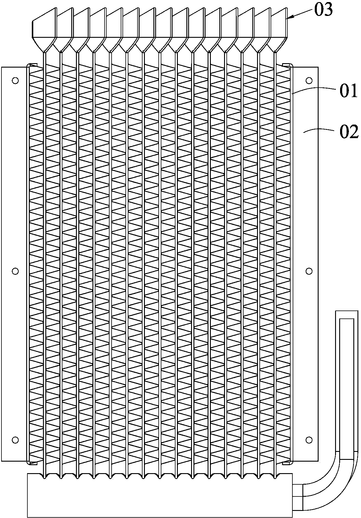
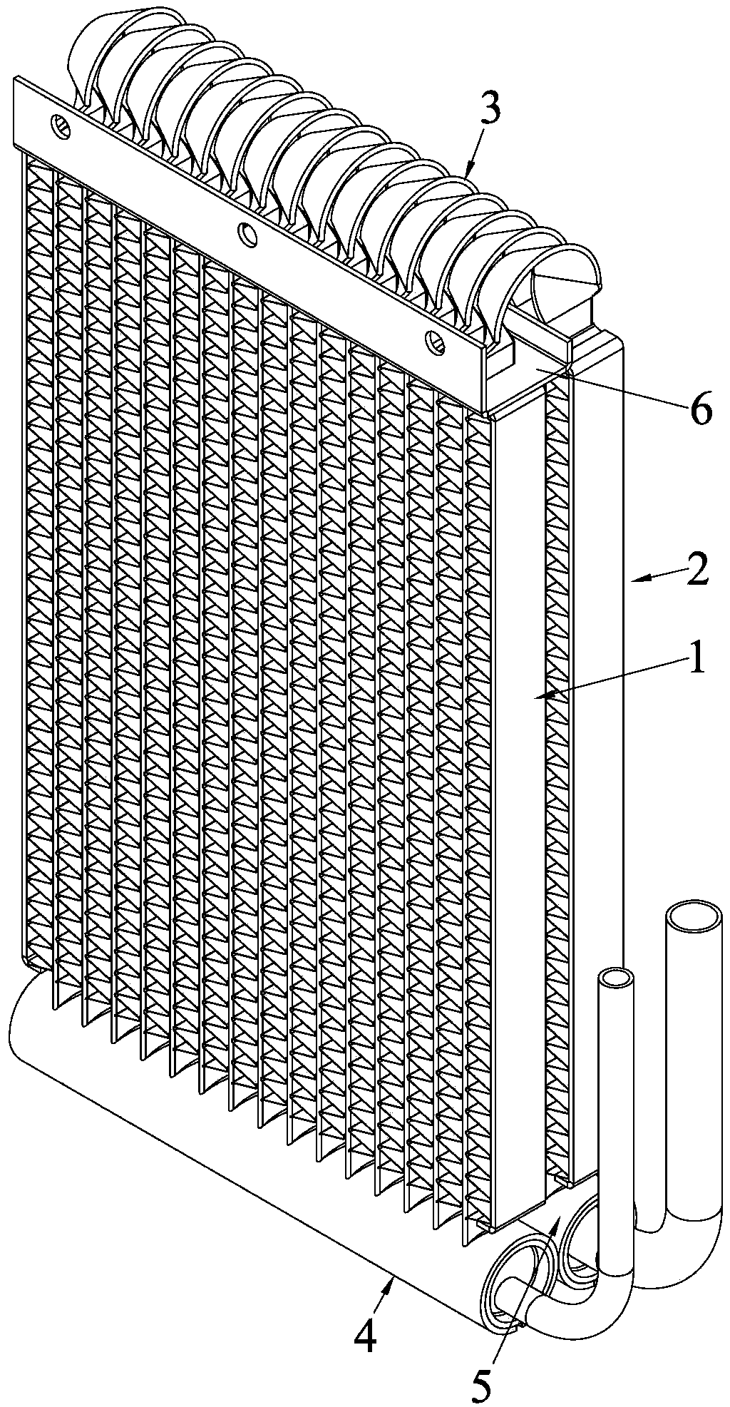
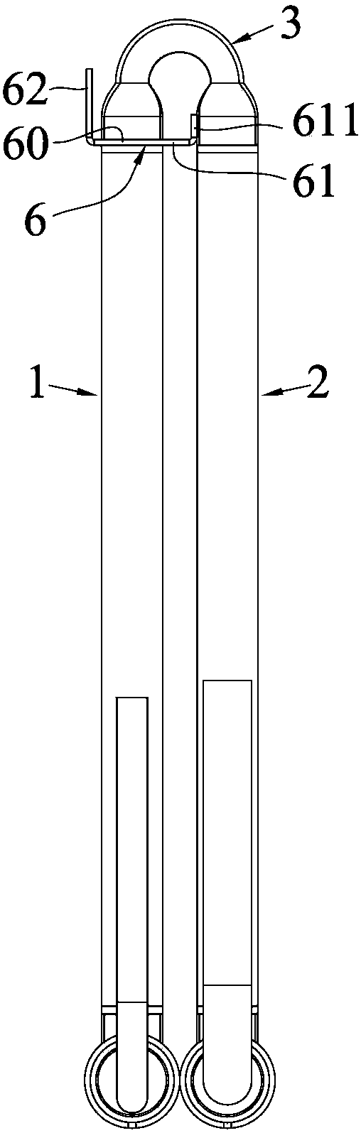
[0034] refer to figure 2 , 3 , the heat exchanger of this embodiment is a double-row microchannel heat exchanger, including two rows of heat exchange cores and flat tube bending parts 3 connected between the two rows of heat exchange cores, and the two rows of heat exchange cores The body is roughly bent to a parallel state. For the convenience of description, the above two rows of heat exchange cores are set as the first heat exchange core 1 and the second heat exchange core 2, but "first" and "second" are only used to distinguish the two rows of heat exchange cores body, has no timing or spatial positioning significance. The flat tube bending part 3 is formed by bending a long flat tube in the middle, but the bending part does not affect the normal circulation of the refrigerant. Usually: the inlet header 4 is connected to the first heat exchange core 1, and the outlet header The flow tube 5 is connected to the second heat exchange core 2, and the refrigerant is distribu...
Embodiment 2
[0045] refer to Figure 5 , the heat exchanger of this embodiment is a double-row microchannel heat exchanger, including two rows of heat exchange cores and flat tube bending parts 3 connected between the two rows of heat exchange cores, and the two rows of heat exchange cores The bodies are roughly bent to a parallel state, and a flow blocking member is provided between the first heat exchange core 1 and the second heat exchange core 2. The difference is that the flow resistance includes two partitions. For the convenience of description, The two partitions are defined as a first partition 7 and a second partition 8, the first partition 7 has a first blocking portion 72 and a first fixing portion 71, and the second partition 8 has a second blocking portion 82 and the second fixing part 81, the first fixing part 71 fixes the first separator 7 to the flat tube of the first heat exchange core 1, and the second fixing part 81 fixes the second separator 8 to the second heat exchan...
Embodiment 3
[0049] Referring to Figure 6(a), the heat exchanger of this embodiment is a double-row microchannel heat exchanger, including two rows of heat exchange cores and flat tube bending parts 3 connected between the two rows of heat exchange cores, The two rows of heat exchange cores are bent to a predetermined angle, and a baffle is provided between the first heat exchange core 1 and the second heat exchange core 2. The baffle includes a first baffle 7 and a second baffle. plate 8, the first partition 7 has a first blocking portion 72 and a first fixing portion 71, the second partition 8 has a second blocking portion 82 and a second fixing portion 81, the first partition 7 and the second partition The specific structure and installation method of the plate 8 can refer to the schemes described in the first and second embodiments, and will not be repeated in this embodiment. The difference is that the first blocking part 72 and the second blocking part 82 are only overlapped together...
PUM
 Abstract
Description
Claims
Application Information
 - R&D
- Intellectual Property
- Life Sciences
- Materials
- Tech Scout
- Unparalleled Data Quality
- Higher Quality Content
- 60% Fewer Hallucinations
Browse by: Latest US Patents, China's latest patents, Technical Efficacy Thesaurus, Application Domain, Technology Topic, Popular Technical Reports.
© 2025 PatSnap. All rights reserved.Legal|Privacy policy|Modern Slavery Act Transparency Statement|Sitemap|About US| Contact US: help@patsnap.com