Round tube, tube and fin heat exchanger with streamlined variable amplitude corrugated fins

A corrugated fin and streamlined technology, applied in the field of round tube fin heat exchanger fins, can solve the problems of large resistance and no obvious improvement of fluid flow linearity, etc.

Active Publication Date: 2016-04-06
LANZHOU JIAOTONG UNIV
View PDF5 Cites 0 Cited by
  • Summary
  • Abstract
  • Description
  • Claims
  • Application Information

AI Technical Summary

Problems solved by technology

Therefore, the existing fin-enhanced heat transfer technology does not significantly improve the flow linearity of the fluid flowing in the tube bundle and the channel formed by the fins, so that the resistance of the fluid flowing through the tube is relatively large.

Method used


Image

  • Round tube, tube and fin heat exchanger with streamlined variable amplitude corrugated fins

Examples


Embodiment Construction

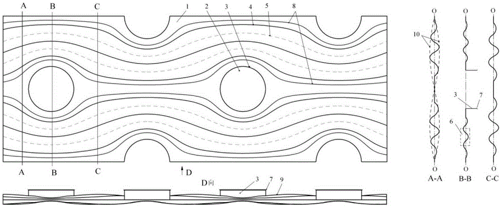
[0018] see figure 1 , the present invention includes a round tube hole 2 on the fin 1 , a ring flanging 3 , a stamped streamlined convex corrugation 4 , a streamlined concave corrugation 5 and a corrugated shape 6 . The round tube holes 2 can be arranged in a fork row or in a straight row. The height of the ring flanging 3 is equal to the pitch of the fins, which plays the role of positioning the fins. The top of the ring flanging 3 is slightly turned outwards to have a flanging 7, which is convenient for the fins to pass through the tube and the fins to be positioned. The streamlined convex corrugations 4 (solid lines) and the streamlined concave corrugations 5 (dotted lines) are alternately distributed between the corrugated area boundaries 8 according to the flow function value, and are distributed symmetrically about the longitudinal and transverse centerlines of the circular pipe hole 2 respectively. The streamlined convex corrugations 4 and the streamlined concave corr...


PUM


Abstract

Disclosed is a streamline variable-amplitude wavy fin for a round tube fin heat exchanger. Streamline convex waves 4 and streamline concave waves 5 which are arranged in a convex-concave interval mode are continuously stamped on fins 1 from an air flow inlet to an outlet according to streamline trends. Connection lines of the same wave troughs and wave crests are all streamlines. Wave amplitudes vary according to the needed waveform in a longitudinal direction. The amplitudes of transverse different waves vary in a mode of a needed waveform enveloping wave troughs and crests. The largest amplitude of convex waves 4 and concave waves 5 is 0.1-0.9 time the interval of the fins. The cross sections of the waves can be of any needed shape. The streamlines are streamlines which enable backflow at tube ends to be avoided in a direction from the tube axis to central cross section in a side channel of a tube fin heat exchanger plate fin corresponding to the fins 1. When liquid flows between the streamline wavy fins, part of the liquid flows in streamline channels formed by the convex waves and the concave waves, transverse changes and changes along the streamlines of the wave amplitudes reduce wall shear stress of flowing and pressure loss of flowing can be evidently reduced.

Description

technical field [0001] The invention relates to fins of a circular tube-tube-fin heat exchanger, in particular to a streamlined variable-amplitude corrugated fin of a circular tube-tube-fin heat exchanger. Background technique [0002] Tube-fin heat exchangers are widely used. The outer side of this type of heat exchanger tube is generally a gas working fluid. In order to reduce the thermal resistance of the gas side, fins are usually installed on the outer side of the tube to increase the heat exchange area and reduce the thermal resistance of the air side. Due to the limitations of heat exchanger volume, economy and fin fin efficiency, it is necessary to further improve the heat transfer performance of round tube fin heat exchangers. The current technology usually makes the fin surface into a structural shape that is conducive to increasing fluid disturbance, such as fins such as louvers, transverse corrugations, vortex generators, intermittent annular grooves, and diamon...

Claims


Application Information

Patent Timeline
Patent Type & Authority Patents(China)
IPC IPC(8): F28F1/32
Inventor 王良璧常立民林志敏武祥宋克伟胡万玲王良成张昆苏梅张强郭鹏王天鹏周文和王烨张永恒王小见刘松
Owner LANZHOU JIAOTONG UNIV
Why Eureka
Try Eureka