
Bole pitch measurement apparatus

A measuring device and a technology of hole distance, which is applied in the direction of mechanical clearance measurement, etc., can solve the problems of large measurement error, low measurement accuracy, and low measurement accuracy, and achieve the effect of eliminating subjective judgment errors, high measurement accuracy, and simple operation

Inactive Publication Date: 2014-10-22
湖北精工钢结构有限公司
View PDF10 Cites 6 Cited by
  • Summary
  • Abstract
  • Description
  • Claims
  • Application Information

AI Technical Summary

Problems solved by technology

[0002] At present, in the construction steel structure industry, for the measurement of the distance between the drilled bolt holes on the component, a steel tape is generally used to measure the distance from the edge of the hole to the edge of another hole. This method is greatly affected by the subjective judgment of the surveyor. low measurement accuracy
[0003] Chinese invention patent application "A device for measuring the distance between bolt holes" (publication number: CN62679846A) discloses a device for measuring the distance between bolt holes, including two hole plugs and a ruler, which are used to directly detect the hole distance, but there is no Setting the mark corresponding to the center of the bolt hole requires human eyes to judge the position of the center of the bolt hole, resulting in large measurement errors and low measurement accuracy; in addition, the bottom of the hole plug is a cylindrical structure, which is only suitable for fixed-size The distance measurement of the bolt hole, the scope of application is small

Method used


Image

  • Bole pitch measurement apparatus
  • Bole pitch measurement apparatus
  • Bole pitch measurement apparatus

Examples


Embodiment Construction

[0018] The implementation of the present invention will be described in detail below in conjunction with the accompanying drawings, but they do not constitute a limitation to the present invention, and are only examples. At the same time, the advantages of the present invention will become clearer and easier to understand.

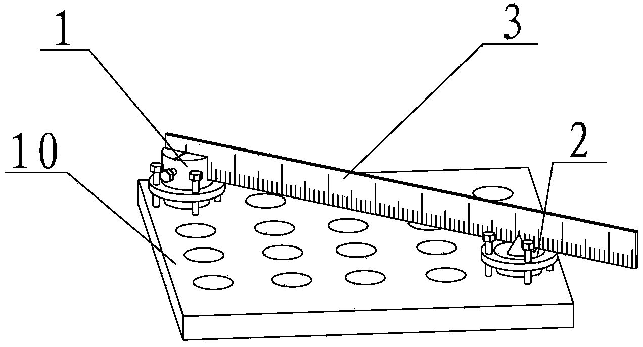
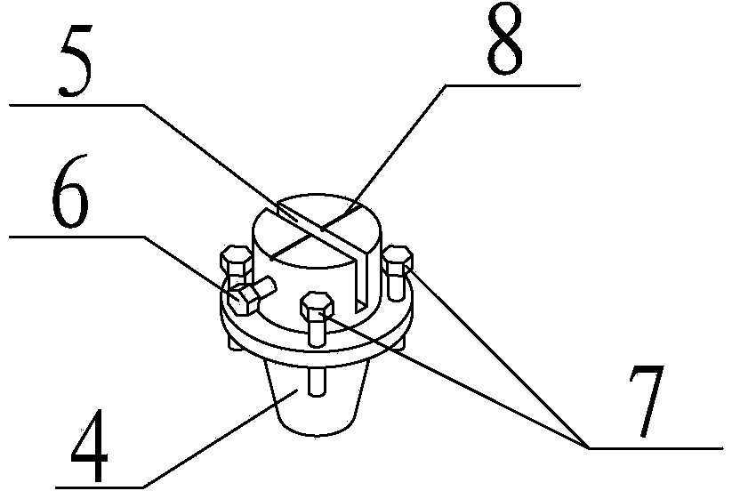
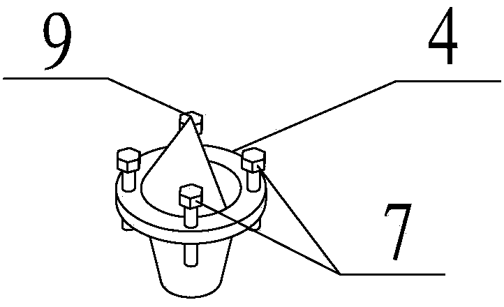
[0019] refer to Figure 1 to Figure 3 It can be seen that the bolt hole distance measuring device of the present invention includes a hole plug 1 at the starting end, a hole plug 2 at the reading end and a ruler 3 . The upper part of the starting end hole plug 1 is a cylindrical structure, the middle part is an annular circular platform 4, and the lower part is a conical structure with a large upper part and a smaller lower part. The top of the hole plug 1 at the starting end is radially provided with a ruler slot 5, and the wall of the ruler slot 5 is provided with a ruler fixing bolt 6. flat. A zero reference slot 8 is provided at the center of the to...


PUM


Abstract

The invention relates to a bole pitch measurement apparatus comprising a starting end hole plug (1), a reading end hole plug (2) and a ruler (3). The apparatus is characterized in that the upper portion of the starting end hole plug (1) has a cylindrical structure; and a clamp groove is formed in the top at the radial direction. The upper portion of the reading end hole plug (2) has a semi-cone-shaped structure; and a pointer (9) is formed at the tip point of the top of the cone. Annular circular truncated cones (4) are formed at the middle portions of the starting end hole plug (1) and the reading end hole plug (2); and the lower portions have the cone-shaped structures with the large upper portions and small lower portions. One end of the ruler (3) is arranged in the ruler clamp groove (5) of the starting end hole plug (1) and the other end is placed at the annular circular truncated cone (4) of the reading end hole plug (2). According to the invention, the structure is simple; the measurement precision is high; and the application range is wide. The measurement of the hole pitch is not influenced by the subjective judgment of the measurement screw, so that the pitch measurement becomes precise, visual and objective.

Description

technical field [0001] The invention relates to the field of steel structure manufacturing and processing, more specifically it is a bolt hole distance measuring device. Background technique [0002] At present, in the construction steel structure industry, for the measurement of the distance between the drilled bolt holes on the component, a steel tape is generally used to measure the distance from the edge of the hole to the edge of another hole. This method is greatly affected by the subjective judgment of the surveyor. The measurement accuracy is low. [0003] Chinese invention patent application "A device for measuring the distance between bolt holes" (publication number: CN62679846A) discloses a device for measuring the distance between bolt holes, including two hole plugs and a ruler, which are used to directly detect the hole distance, but there is no Setting the mark corresponding to the center of the bolt hole requires human eyes to judge the position of the cente...

Claims


Application Information

Patent Timeline
IPC IPC(8): G01B5/14
Inventor 张发荣何志涛姜殿忠程登张林
Owner 湖北精工钢结构有限公司
Learn More