Mirror surface display device

A technology of display device and main display, applied in nonlinear optics, instruments, optics, etc., can solve the problem that light cannot be emitted

Inactive Publication Date: 2014-10-22
BOE TECH GRP CO LTD
View PDF4 Cites 16 Cited by
  • Summary
  • Abstract
  • Description
  • Claims
  • Application Information

AI Technical Summary

Problems solved by technology

At this time, the main display panel 100 is not turned on, and the light cannot pass through the main display panel 100 to emit

Method used


Image

  • Mirror surface display device
  • Mirror surface display device
  • Mirror surface display device

Examples


Embodiment Construction

[0024] Specific embodiments of the present invention will be described in detail below in conjunction with the accompanying drawings. It should be understood that the specific embodiments described here are only used to illustrate and explain the present invention, and are not intended to limit the present invention.

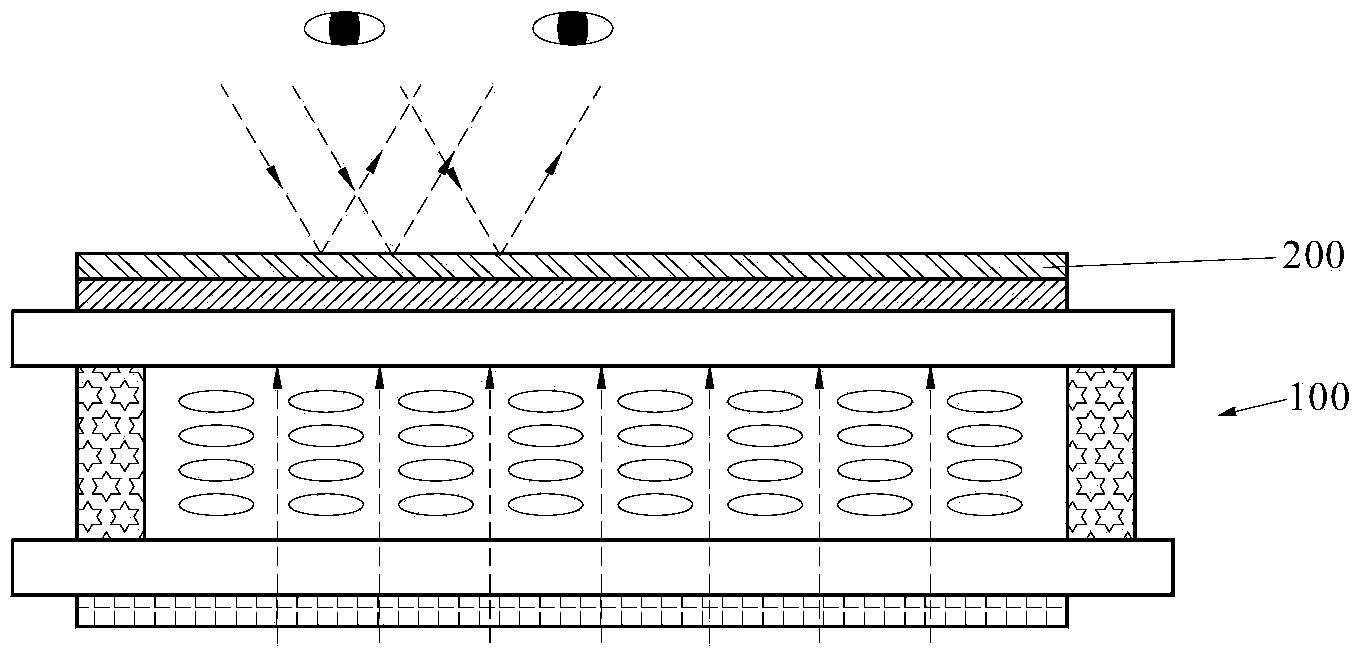
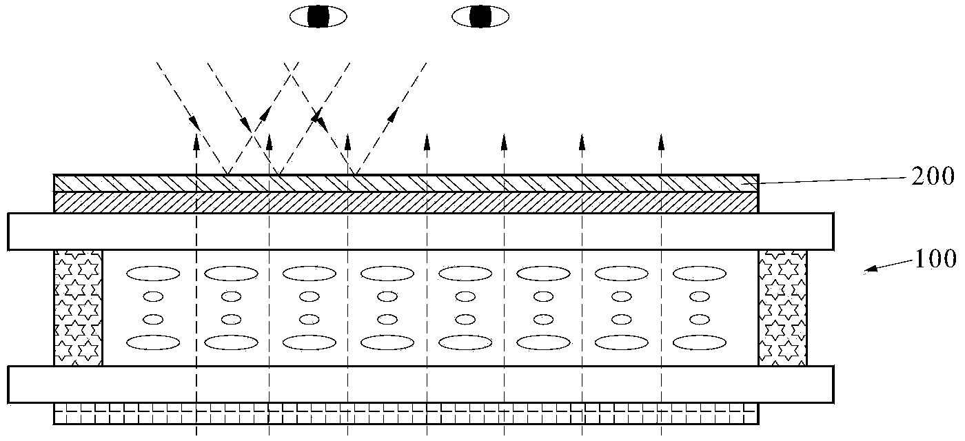
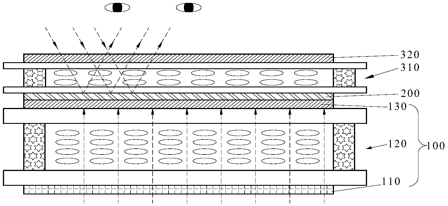
[0025] Such as image 3 and Figure 4 As shown, the present invention provides a mirror display device, the mirror display device includes a main display panel 100, wherein the mirror display device also includes an auxiliary display panel, the auxiliary display panel includes a phase retardation liquid crystal cell 310, arranged at the phase An auxiliary polarizer 320 on one surface of the retardation liquid crystal cell 310 and a transflective film 200 disposed on the other surface of the retardation liquid crystal cell 310 .

[0026] In the region where an electric field is applied to the phase retardation liquid crystal cell 310, the incident light enterin...


PUM


Abstract

The invention provides a mirror surface display device. The mirror surface display device comprises a main display panel and an auxiliary display panel. The auxiliary display panel comprises a phase delay liquid crystal box, an auxiliary polaroid arranged on one surface of the phase delay liquid crystal box and a semi-transparent and semi-reflecting film arranged on another surface of the phase delay liquid crystal box. The semi-transparent and semi-reflecting film is attached to the light output surface of the main display panel. In the area, with an electric field loaded, of the phase delay liquid crystal box, incident rays input through the auxiliary polaroid can be converted into emergent rays through the auxiliary polaroid, liquid crystals in the phase delay liquid crystal box and the semi-transparent and semi-reflecting film, and the propagation direction of the emergent rays is perpendicular to the direction of a light-transmitting shaft of the auxiliary polaroid. In the area, without the electric field loaded, of the phase delay liquid crystal box, the incident rays reach the semi-transparent and semi-reflecting film through the liquid crystals in the phase delay liquid crystal box and are reflected and output. According to the mirror surface display device, the semi-transparent and semi-reflecting film does not influence displaying of the main display panel.

Description

technical field [0001] The invention relates to the field of daily necessities, in particular to a mirror display device. Background technique [0002] figure 1 and figure 2 Shown in is a mirror display device that can be used as a mirror. Such as figure 1 and figure 2 As shown, the mirror display device includes a main display panel 100 and a transflective film 200 attached on the main display panel 100 . figure 1 and figure 2 The dotted arrows in show the direction of light propagation. [0003] figure 1 Shown is a schematic diagram of the mirror display device used only as a mirror. At this time, the main display panel 100 is not turned on, and the light cannot pass through the main display panel 100 to emit. The light irradiated on the semi-transparent and semi-reflective film 200 of the mirror display device is reflected by the semi-transparent and semi-reflective film and enters human eyes. Therefore, the mirror display device can be used only as a mirror. ...

Claims


Application Information

Patent Timeline
Patent Type & Authority Applications(China)
IPC IPC(8): G02F1/1335G02F1/13363
Inventor 方正崔贤植李会田允允王海燕
Owner BOE TECH GRP CO LTD
Why Eureka
Try Eureka