
Intelligent power module and manufacturing method thereof

A technology of intelligent power module and manufacturing method, applied in semiconductor/solid-state device manufacturing, semiconductor device, electrical components and other directions, can solve the problems of easy interference, large distance between components, long wiring, etc., to reduce the long wiring , to ensure the sameness, the effect of line reduction

Active Publication Date: 2017-02-15
GD MIDEA AIR CONDITIONING EQUIP CO LTD
View PDF5 Cites 1 Cited by
  • Summary
  • Abstract
  • Description
  • Claims
  • Application Information

AI Technical Summary

Problems solved by technology

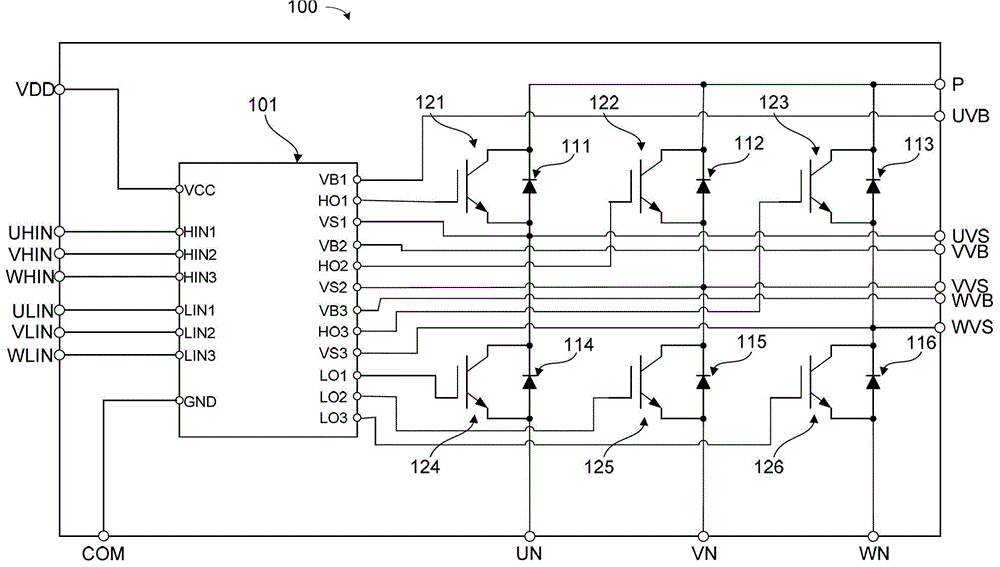
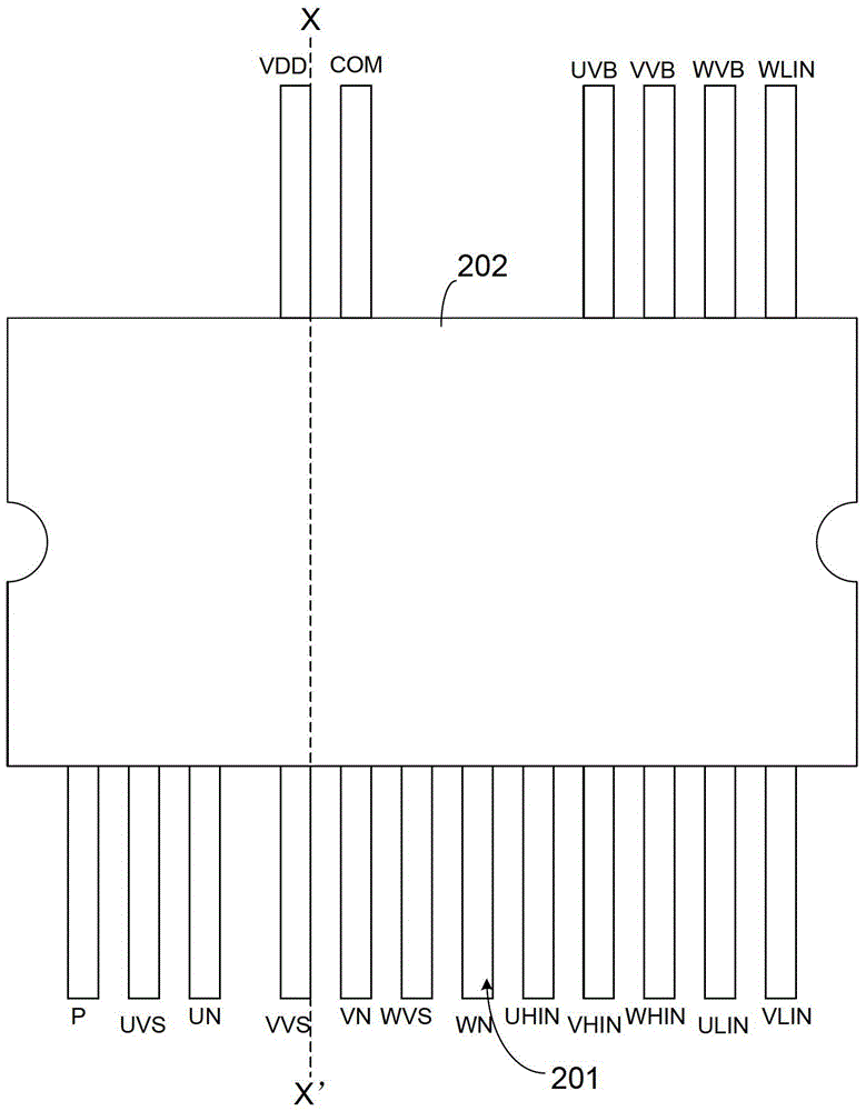
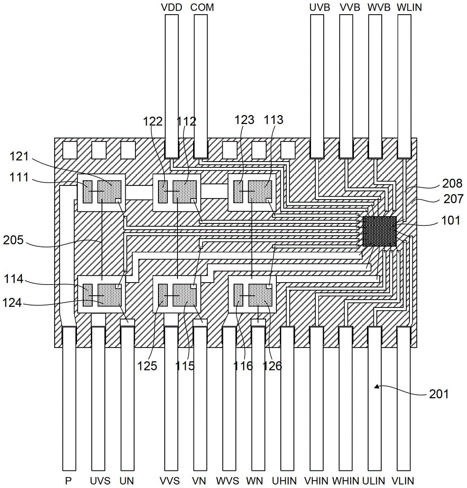
[0010] from Figure 1(C) It can be seen that the current intelligent power module controls 6 IGBT tubes by 1 HVIC tube, which leads to long wiring and easy interference between lines; and, because the distance from the HVIC tube to the 6 IGBT tubes is not the same, resulting in 6 IGBT tubes The sameness of driving signal transmission of each IGBT tube is difficult to control; in addition, because too much circuit wiring on the substrate will inevitably increase the area of ​​the substrate, resulting in an increase in the area of ​​the current intelligent power module, which increases the manufacturing cost of the intelligent power module and affects the intelligent power module. The popularity of power modules in the low-end field; in addition, due to the need to reserve a circuit wiring area, the distance between components is relatively large, and the bonding wires connecting components through metal wires are relatively long, which affects the reliability of the bonding wires. And there is a risk of causing flushing during the molding process

Method used


Image

  • Intelligent power module and manufacturing method thereof
  • Intelligent power module and manufacturing method thereof
  • Intelligent power module and manufacturing method thereof

Examples


Embodiment Construction

[0042] In order to make the technical problems, technical solutions and beneficial effects to be solved by the present invention clearer, the present invention will be further described in detail below in conjunction with the accompanying drawings and embodiments. It should be understood that the specific embodiments described here are only used to explain the present invention, not to limit the present invention.

[0043] to combine Figure 2 (A) , 2(B) , 2(C), 2(D), in one embodiment, the intelligent power module 1 includes a metal substrate 306, an insulating layer 307, a circuit wiring layer 308, a plurality of IGBT tubes 20, and FRD tubes having the same number as the IGBT tubes 20 10. The number of gate drive transistors 40 and metal wires 305 is the same as that of the IGBT transistors 20 .

[0044] One surface of the metal substrate 306 is covered with an insulating layer 307 . The circuit wiring layer 308 is formed on the surface of the insulating layer 307 . A pl...


PUM


Abstract

The invention is applicable to electronic device technology, and provides an intelligent power module and a manufacturing method thereof. The intelligent power module includes a metal substrate, one surface of which is covered with an insulating layer; a circuit wiring layer formed on the surface of the insulating layer; a plurality of IGBTs Tubes, arranged at preset positions on the circuit wiring layer; gate drive tubes, the number of which is the same as that of the IGBT tubes, each of the gate drive tubes is used as a drive circuit for the corresponding IGBT tube, and each The driving end of the gate driving transistor is the same as the length of the wiring that is electrically connected to the gate of the IGBT transistor; the metal wire is connected between the circuit wiring layer, the IGBT transistor and the gate driving transistor to form a preset circuit. Ensure that the wiring from the gate drive tube to the gate of the IGBT tube can be made the same, so that the dynamic characteristics of the IGBT tube are the same, and the wiring of the intelligent power module will not be increased.

Description

technical field [0001] The invention belongs to the field of electronic device manufacturing technology, and in particular relates to an intelligent power module and a manufacturing method thereof. Background technique [0002] Intelligent Power Module (IPM) is a power drive product that combines power electronics and integrated circuit technology. IPM integrates power switching devices and high-voltage drive circuits, and has built-in fault detection circuits such as overvoltage, overcurrent and overheating. On the one hand, the IPM receives the control signal of the MCU (Microprogrammed Control Unit, microprogram controller) to drive the subsequent circuit to work, and on the other hand, sends the system status detection signal back to the MCU. Compared with the traditional discrete solution, IPM wins more and more markets with its advantages of high integration and high reliability. It is especially suitable for frequency converters and various inverter power supplies fo...

Claims


Application Information

Patent Timeline
Patent Type & Authority Patents(China)
IPC IPC(8): H01L25/16H01L21/50
CPCH01L2924/13055H01L2224/48137H01L2224/48472H01L2224/49171H01L2924/00
Inventor 冯宇翔
Owner GD MIDEA AIR CONDITIONING EQUIP CO LTD
Learn More