X-ray tube assembly and x-ray computerized tomography scanner

An X-ray tube and tomographic imaging technology, which is applied to X-ray tube electrodes, X-ray tube components, X-ray equipment, etc., can solve problems such as blockage of radiator vents and accumulation

Inactive Publication Date: 2014-10-22
TOSHIBA ELECTRON TUBE & DEVICES
View PDF7 Cites 9 Cited by
  • Summary
  • Abstract
  • Description
  • Claims
  • Application Information

AI Technical Summary

Problems solved by technology

[0012] However, in the case of using the fan unit to blow air toward the radiator, there is a problem that the dust contained in the air accumulates on the radiator during use of the device and blocks the ventilation part of the radiator.

Method used


Image

  • X-ray tube assembly and x-ray computerized tomography scanner
  • X-ray tube assembly and x-ray computerized tomography scanner
  • X-ray tube assembly and x-ray computerized tomography scanner

Examples


Embodiment Construction

[0066] Hereinafter, the X-ray computed tomography apparatus according to Embodiment 1 will be described in detail with reference to the drawings. The X-ray computed tomography apparatus is an X-ray CT (computerized tomography: computerized tomography) apparatus.

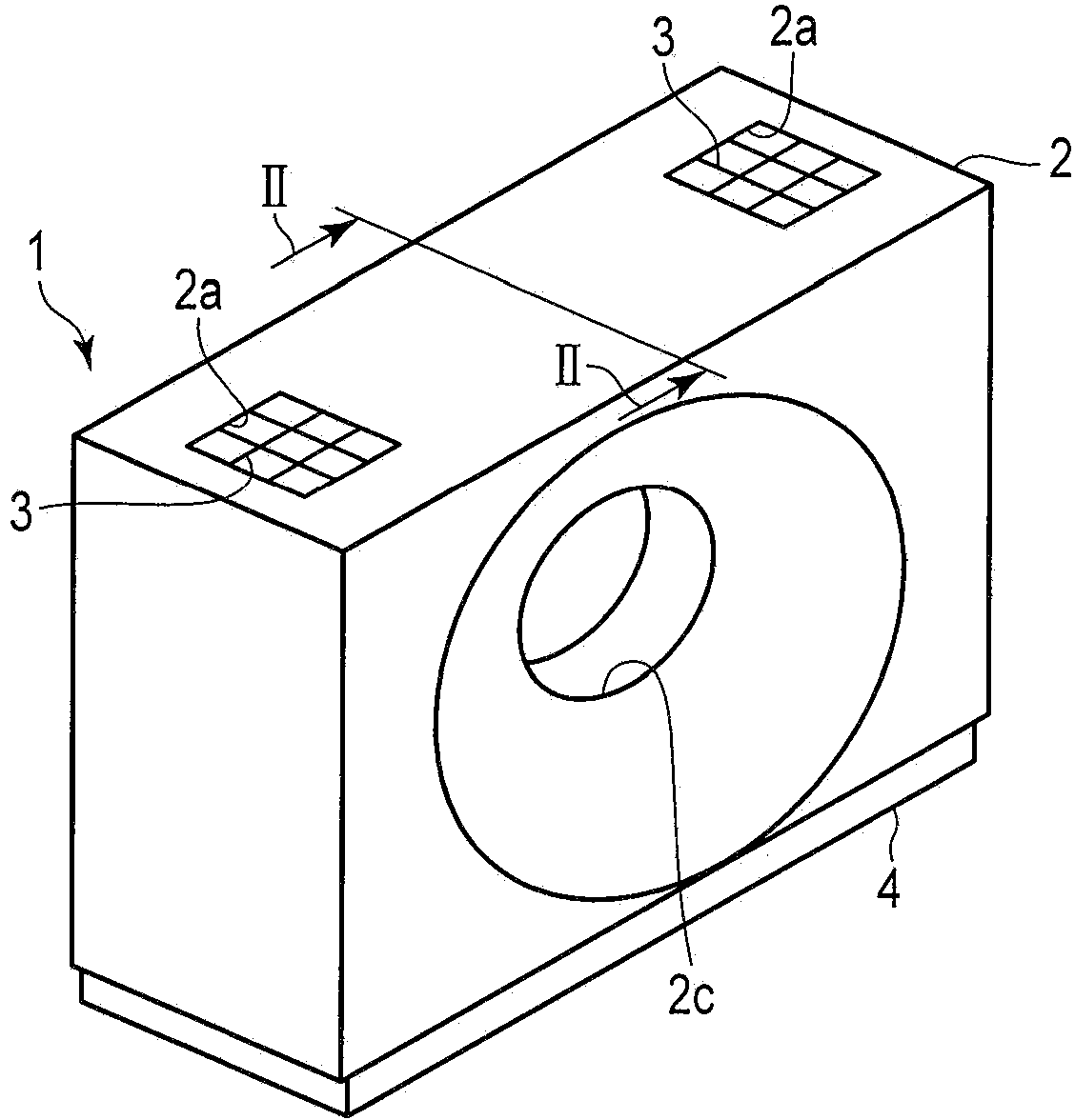
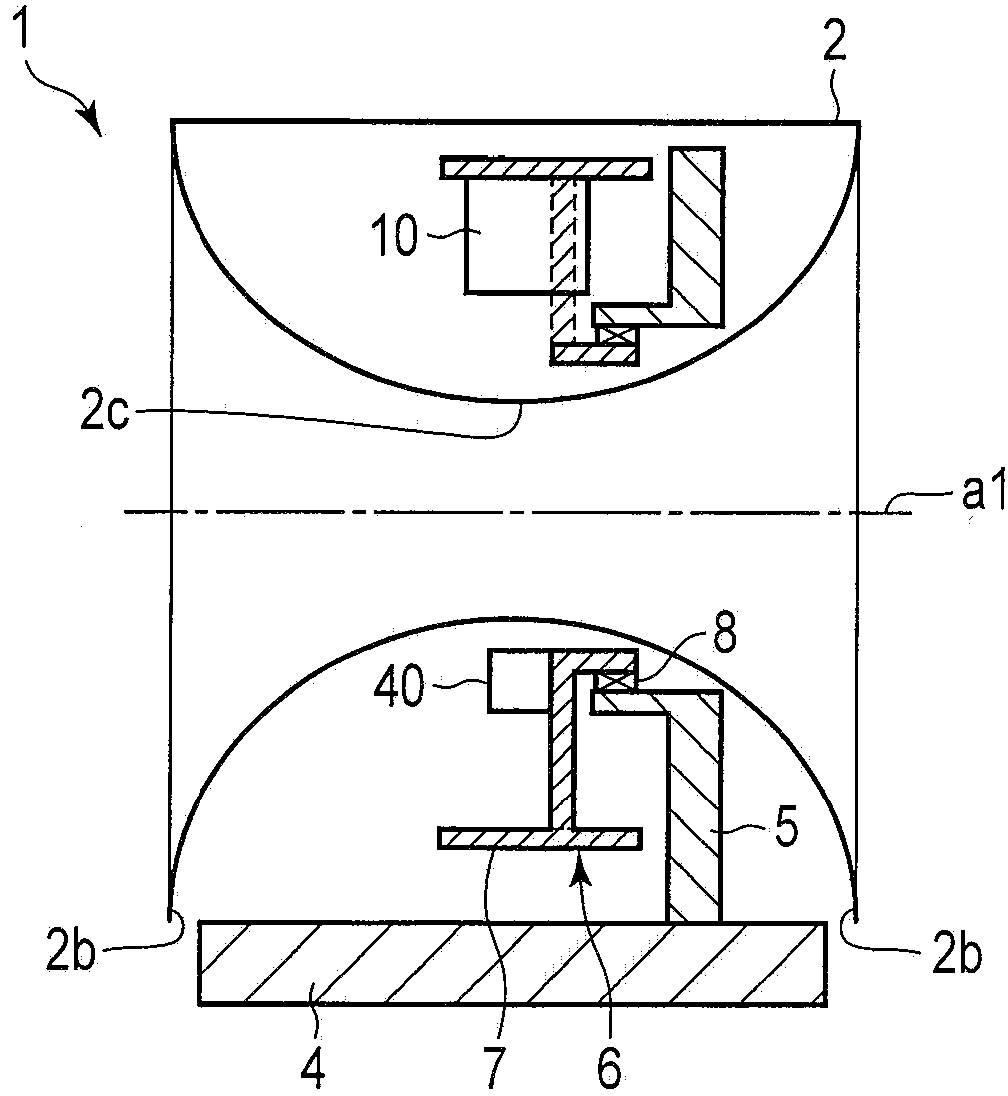
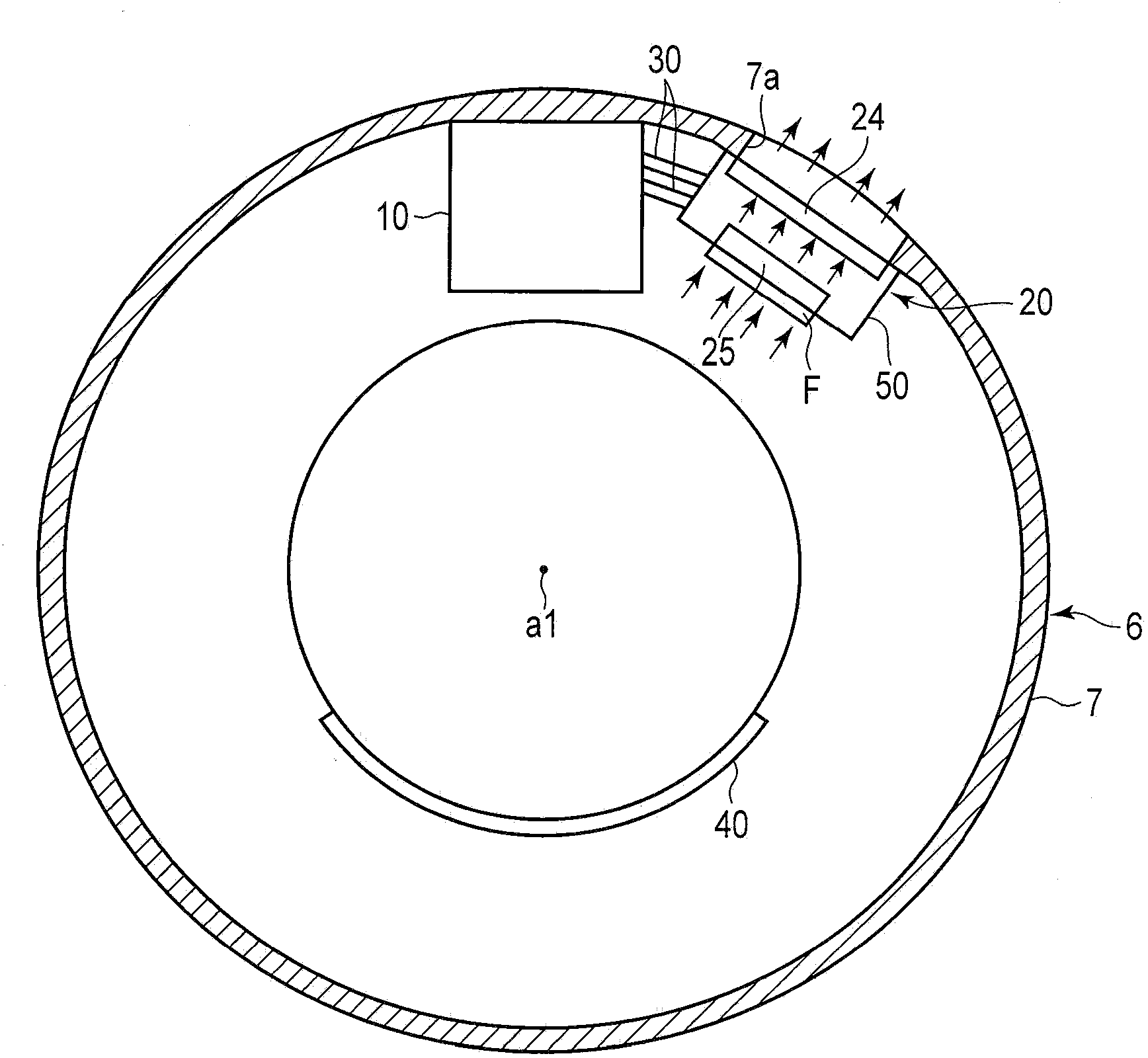
[0067] figure 1 It is a perspective view showing the appearance of the gantry of the X-ray CT apparatus according to the first embodiment. figure 2 is to mean along figure 1 The cross-sectional view of the X-ray CT apparatus obtained by the II-II line. image 3 yes means figure 2 A front view of the rotary stand shown, and the X-ray tube device, cooling unit, and X-ray detector installed on the rotary stand.

[0068] Such as Figure 1 to Figure 3 As shown, the X-ray CT apparatus 1 includes a housing 2 , a base portion 4 , a fixed frame 5 , a rotating frame 6 , a bearing member 8 , an X-ray tube device 10 , a cooling unit 20 , and an X-ray detector 40 .

[0069] The casing 2 accommodates the above-mentioned pl...


PUM


Abstract

According to one embodiment, an X-ray tube assembly includes a housing, an X-ray tube, a coolant to which at least a part of heat generated by the X-ray tube is transferred, a circulation channel through which the coolant is circulated, a circulation pump, a radiator, an air filter and a fan unit. The air filter is formed of a three-dimensional nonwoven fabric that is formed of irregularly tangled resin fibers and provides a three-dimensional structure having a spatial volume ratio of not less than 93%. The air filter permits air to pass therethrough to eliminate dust from the air.

Description

technical field [0001] Embodiments of the present invention relate to an X-ray tube device and an X-ray computed tomography device. Background technique [0002] A gantry of an X-ray computed tomography apparatus (hereinafter referred to as an X-ray CT apparatus) includes a fixed frame, a rotatable gantry rotatably supported by the fixed frame, and a case housing the fixed frame body and the rotatable gantry. The gantry also includes an X-ray tube device, an X-ray detector, and a cooling unit (cooler) mounted on the rotating gantry. [0003] More specifically, the rotary gantry has an annular frame portion, and an X-ray tube device, an X-ray detector, a cooling unit, and the like are attached to the inner wall of the annular frame. These units are more compact but have a higher mass, and the pressure on the setting surface is higher, so they especially need to be firmly fixed. [0004] By adopting the above structure, even when the rotary gantry rotates at a high speed and...

Claims


Application Information

Patent Timeline
Patent Type & Authority Applications(China)
IPC IPC(8): H05G1/02A61B6/03
CPCH01J35/12G01N23/046A61B6/032A61B6/4488H01J35/13
Inventor 渡边未树石原智成阿武秀郎井出秀树
Owner TOSHIBA ELECTRON TUBE & DEVICES
Why Eureka
Try Eureka