
Method for determining the concentration of an element in a material

An element and content technology, applied in the direction of material analysis using radiation, analyzing materials, and material analysis using wave/particle radiation, can solve problems such as unsatisfactory results and low mercury content

Inactive Publication Date: 2014-10-22
E·克茨
View PDF4 Cites 3 Cited by
  • Summary
  • Abstract
  • Description
  • Claims
  • Application Information

AI Technical Summary

Problems solved by technology

For example, a well-known problem is the need to measure the total ash content in coal
However, it turns out that the results of online measurements using XRF techniques are not satisfactory because the mercury content of real-life samples is very low

Method used


Image

  • Method for determining the concentration of an element in a material
  • Method for determining the concentration of an element in a material
  • Method for determining the concentration of an element in a material

Examples


no. 1 approach

[0038] An advantage over the first embodiment is that the detector need not be energy dispersive and a multi-channel analyzer is not necessary.

[0039] The operation is as follows:

[0040] First, apply the well-known general formula:

[0041] I=I 0 *e -μ*ρ*d (1)

[0042] in

[0043] I 0 = incident energy

[0044] I = measured energy

[0045] μ = absorption coefficient

[0046] so

[0047]

[0048] as well as

[0049]

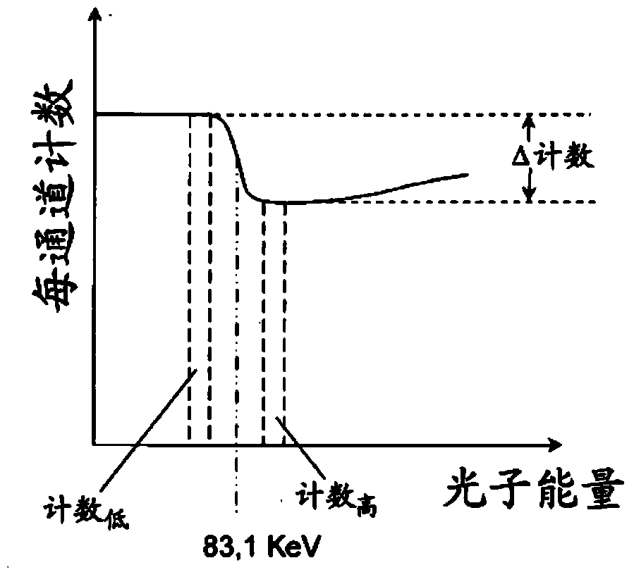
[0050] And, for measurements using a Cs source,

[0051] as from Figure 4 as can be seen

[0052] mu HG =μ 高 -μ 低

[0053] this gets

[0054]

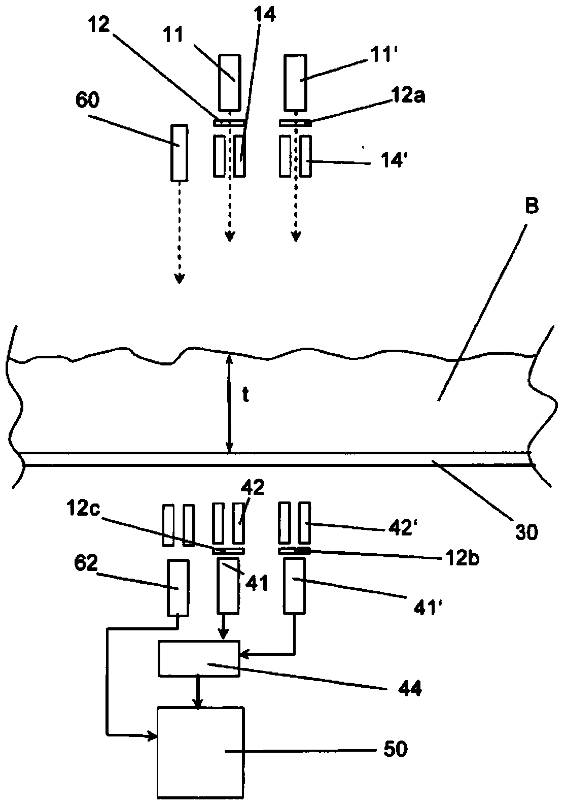
[0055] Figure 5 shown in Figure 4 changes in . Here, a normal detector 45 and a discriminator 65 are used. Am-241 source 11 and Cd-109 source 11 ′ are directed to this common detector 45 and the energy is separated by discriminator 65 .

[0056] Image 6 shown in Figure 5 changes in . Here, the beam of the Cd-109 source 11' is extended through the Am-241 source 11 so that both be...


PUM


Abstract

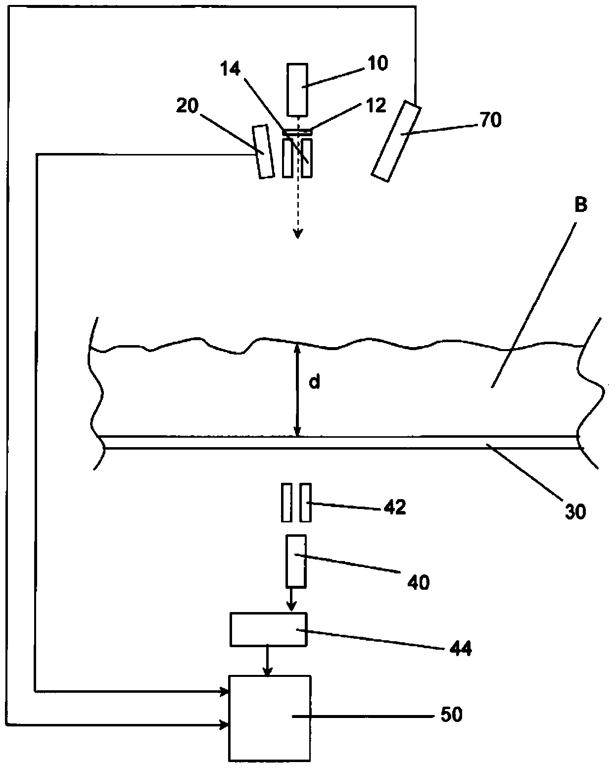
A method for determining the concentration of an element in a material includes irradiating the material with an X-ray beam having a continuum in the area of an absorption edge of the element to be measured. The intensity of the transmitted X-ray beam is measured with an energy dispersive sensor. The intensity of the transmitted X-ray beam in an energy interval above the absorption edge and in an energy interval below the absorption edge is determined. The concentration of the element is computed on the basis of said intensities.

Description

technical field [0001] The invention relates to a method for determining the content of at least one element in a material. Background technique [0002] In many industrial applications it is necessary to determine the content of one or more elements in a matrix material. Often, it is necessary or at least desirable to determine the content in an on-line measurement. For example, a well-known problem is the need to measure the total ash content in coal. Here, the total ash content is generally in the range of 1% to 50%. There are established techniques for how measurements are made to determine total ash content. The most common method is the so-called dual energy method. The sample is irradiated with two X-ray or gamma-ray beams of different energies. The transmission is measured, and the area weight and average atomic number are determined. If the composition of the ash is known, then the ash content of the coal can be calculated. In a more sophisticated method, the...

Claims


Application Information

Patent Timeline
Patent Type & Authority Applications(China)
IPC IPC(8): G01N23/09G01N23/12G01N23/087
CPCG01N23/12G01N23/087G01N23/09
Inventor A·克莱因
Owner E·克茨
Learn More