ion therapy machine
A treatment machine and ionization technology, applied in the field of treatment instruments, can solve the problems of affecting treatment efficiency, damage to the connecting part of the telescopic structure, and shortening the service life of the treatment instrument, and achieve the effects of improving the service life and facilitating the arrangement and storage.
- Summary
- Abstract
- Description
- Claims
- Application Information
AI Technical Summary
Problems solved by technology
Method used
Image
Examples
Embodiment 1
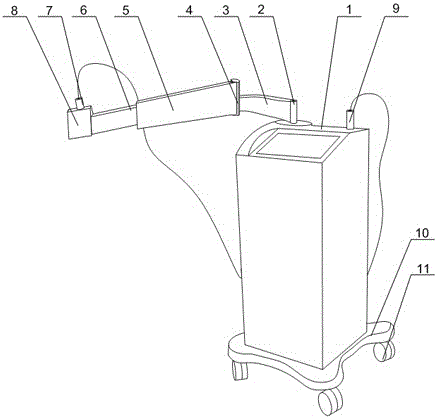
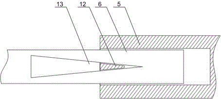
[0021] Such as Figure 1 to Figure 3 As shown, the present embodiment includes a treatment machine body, on which a B probe 9 and a freely rotating rotating column 2 are arranged, and the rotating column 2 is connected with a fixed rod 5 through a rotating plate 3, and the fixed rod 5 There is a cavity inside, and one end of the telescopic rod 6 is slidably arranged in the cavity, and the middle part of the telescopic rod 6 is provided with an acute-angled triangular hole 13, and the inner wall of the middle part of the cavity is connected with a top angle matching triangular hole 13. The limit block 12 also includes a storage platform 8 and an A probe 7 placed on the storage platform 8 , and the storage platform 8 is connected with the other end of the telescopic rod 6 . The present invention is as the improvement to the telescoping structure of the probe bracket of the existing therapeutic apparatus, the rotating column 2 that rotates freely on the therapeutic apparatus body...
Embodiment 2
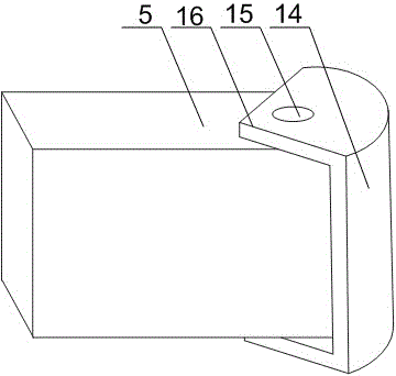
[0023] Such as figure 1 and image 3 As shown, on the basis of Embodiment 1, this embodiment also includes a limiting structure 4, the limiting structure 4 includes a bow-shaped plate 14 and baffles 16 arranged at both ends of the bow-shaped plate 14, the outer wall of the bow-shaped plate 14 and the rotation The plates 3 are connected, and the fixed rod 5 is rotated through the rotating shaft 15 and installed in the space formed by the arched plate 14 and the two baffles 16. When the fixed rod rotates around the rotating shaft, the two sides of the arched plate are located on the movement track of one end of the fixed rod close to the arched plate. . The inner side of the arched plate 14 is rotationally connected with the fixed rod 5 through the rotating shaft 15, and the outer side of the arched plate 14 is connected with the rotating plate 3. Through the rotating shaft 15 and the rotating column 2, the multi-angle movement of the storage table 8 in the horizontal operating...
PUM
 Abstract
Description
Claims
Application Information
 - R&D
- Intellectual Property
- Life Sciences
- Materials
- Tech Scout
- Unparalleled Data Quality
- Higher Quality Content
- 60% Fewer Hallucinations
Browse by: Latest US Patents, China's latest patents, Technical Efficacy Thesaurus, Application Domain, Technology Topic, Popular Technical Reports.
© 2025 PatSnap. All rights reserved.Legal|Privacy policy|Modern Slavery Act Transparency Statement|Sitemap|About US| Contact US: help@patsnap.com


